
Estimated Study Time: 16 minutes
Directional earth fault protection
This technical article continues the series of articles dedicated to mastering single line and wiring diagrams of medium voltage switchgear. This time, the subject is the principle, and realization of earth fault protection applied to the same example switchgear used in the previous article. The focus of this article will be on directional earth fault.
 Mastering single line and wiring diagrams: MV earth fault protection
If you didn’t read the previous article in this series, you can find it here.
There are numerous variations of MV switchgear topology, measurement, and control logic. However, there are also some basic rules related to these aspects which may be frequently seen in practice, with the purpose of increased safety and reliability during operation. Within this article, the real example of MV switchgear with two main busbar sections will be described.
Most of the attention will be given to concrete practical solutions related to some protection and measuring issues. This subject will be illustrated by use of adequate single line and wiring diagrams.
Example of MV switchgear
Switchgear which is the subject of this example is installed inside MV/LV substation, and serving for power supply of new factory of construction steel products. There are eight MV/LV power transformers in total, with rated power of 3.5 MVA each.
Table 1 – Main technical characteristics of MV switchgear
| Construction: | Metal enclosed |
| Installation type: | Indoor |
| Isolation type: | Air insulated (isolation medium inside cubicles) |
| Protection degree: | IP 3X |
| Ambient temperature: | −5 … +40 °C |
| Number of cubicles: | 14 |
| Rated voltage: | 24 kV (*) |
| Operating voltage: | 20 kV (*) |
| Rated lightning withstand voltage: | 125 kV, 1.2/50 µs |
| Rated power frequency withstand voltage: | 50 kV, 1 min. |
| Rated current of main busbars: | 1250 A |
| Rated short time withstand current: | 20 kA × 2 s |
| Rated peak withstand current: | 50 kA |
| Arc test current: | 21 kA × 1 s (**) |
| Internal arc classification (IAC): | AFLR (**) |
| Rated voltage of control and signal circuits: | 110 VDC |
(*) Rated voltage of the switchgear is the upper limit of phase to phase RMS value which switchgear is capable to withstand continuously. Operating voltage is rated (expected) phase to phase value during operation. This value is usually allowed to vary within ±10% limits or less.
(**) IAC parameter defines from which sides MV switchgear is safely accessible during internal fault followed by presence of electric arc. This parameter depends on arc test current value, dimensions of room inside of which MV switchgear is installed, and technical measures taken for dissipation of heat and pressure caused by arc.
In this case, so called gas duct is used for that purpose. Meaning of IAC designation is as follows:
- A – MV switchgear may be accessed by instructed (technical) personnel
- FLR – MV switchgear may be safely accessed from front (F), lateral (L) and rear (R) side
Block diagram of MV switchgear can be seen in Figure 1. It can be supplied from two independent sources (substation 110/20 kV and substation F), that is why two incoming cubicles (1J07 and 1J10) are used. These two incoming cubicles cannot be active (closed) at the same time, i.e. parallel operation of two incoming lines is forbidden.
There are eight transformer cubicles (1J02 – 1J06 and 1J11 – 1J13), bus section cubicle (1J08), bus riser cubicle (1J09) and two spare/measurement cubicles (1J01 and 1J14).
Circuit breaker is used as major switching and protection device inside every cubicle. This is practically mandatory if selectivity and more complex protection functions need to be achieved inside larger MV supply system.
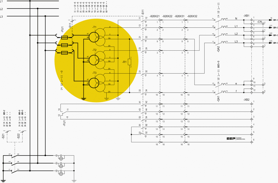
Principle and realization of earth fault protection
Every cubicle which contains the circuit breaker, except the one inside bus section cubicle (1J08), is equipped with protection relay and two types of current transformer: one for overcurrent protection, and other for earth fault protection. Incoming cubicles (1J07 and 1J10) are also equipped with current transformers for measuring. Voltage transformers are placed inside cubicles (1J01) and (1J14), at the end of both busbar sections.
Why there are exactly two voltage transformers for the whole switchgear?
In general, for MV applications, one voltage transformer per each section of mutually connected busbars is used. In our case, the switchgear can be supplied from two separate sources (substation 110/20kV and substation F) with bus section circuit breaker open.
Related electrical guides & articles


Miodrag Kokotovic
Graduated from Faculty of Electrical Engineering, within University of Belgrade, in the field of electrical power systems. Expert in electrical part of tender preparation, design, procurement, construction and commissioning of treatment plants and pumping stations, electrical power quality and energy management.Profile: Miodrag Kokotovic
