
Estimated Study Time: 10 minutes
MCC Circuit for Critical Motors
An MCC circuit of a motor could be based on the Direct Online Starter (DOL) or Star Delta Starter which has something to do with the requirement of the power system in an industry. But it could have additional logics depending upon the requirement of the process. In that regard, a very important feature of MCC circuits is auto/manual start-up selection for motors.
 MCC Circuit Featuring Auto Re-Closure Relay Functionality
In case of a power interruption of a few minutes followed by power restoration or energization of back-up source in the meantime, it could take long before the control room operator sitting on his desk switches on all the critical motors such as those responsible for the lubrication and barring of turbines, compressors and pumps.
In this manual start-up selection, a re-closing relay setup is incorporated into the circuit, which is nothing but a combination of off-delay and on-delay timers so that when the power recovers in a quick time, the lubrication pump or barring motor starts automatically without the involvement of the operator.
Ok, let’s get into the discussion.
Circuit Diagram
Attached below is the simple DOL starter control circuit diagram of a motor. Let’s dissect the circuit diagram in detail,
Figure 1 – Simple DOL starter control circuit diagram of a motor (click to zoom)
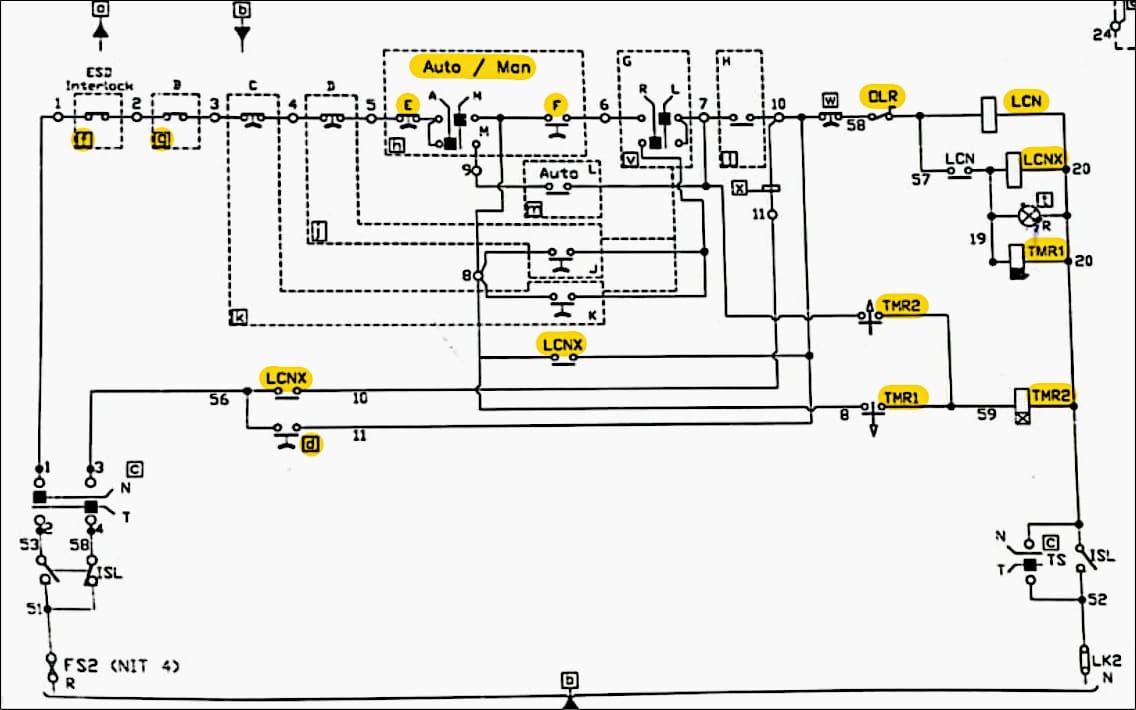
Where:
- Auto / Man – Auto/Manual Selector Switch
- E – Stop Control Switch
- F – Start Control Switch
- OLR – Overload Relay Contact
- f and g – Field Stop Interlocks
- LCN – Main Power Contactor
- LCNX – Auxiliary Contactor
- TMR1 – Off-delay timer
- TMR2 – On-delay timer
- d – Test pushbutton
MCC Circuit on Auto-Mode
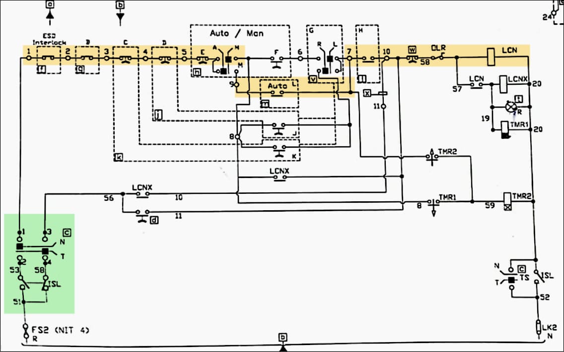
When the breaker is racked in as highlighted in green, the signal is passed through auto contact L to the main power contactor LCN of the motor. This closes the LCN contact thus energizing the auxiliary contactor LCNX and the motor starts.
The off-delay timer TMR1 is also energized at the same time, however, it doesn’t play any role in auto-mode.
Figure 2 – MCC Circuit on Auto-Mode (click to zoom)
Circuit on Manual-Mode
Now let’s understand the working on manual mode and re-closure relay functionality through the below circuit diagram. When the selection is on manual mode, the only thing stopping the motor from starting is “F” as marked in green, which is the start control station installed locally on the field.
Once the start control station “F” is pressed, the signal is passed and the main power contactor LCN latches, thereby, starting the motor.
Related electrical guides & articles


Umer Nasir
I am an electrical engineer specializing in electrical power, with experience in the operation and maintenance of Low- and Medium-voltage electric machinery and switchgear, life assessment testing, troubleshooting, and root cause analysis of various failures associated with electrical machinery.Profile: Umer Nasir
