
Defects in the insulation
The measurement of insulation resistance is a common routine test performed on all types of electrical wires and cables. As a production test, this test is often used as a customer acceptance test, with minimum insulation resistance per unit length often specified by the customer.
The results obtained from IR Test are not intended to be useful in finding localized defects in the insulation as in a true HIPOT test, but rather give information on the quality of the bulk material used as the insulation.
Even when not required by the end customer, many wire and cable manufacturers use the insulation resistance test to track their insulation manufacturing processes, and spot developing problems before process variables drift outside of allowed limits.
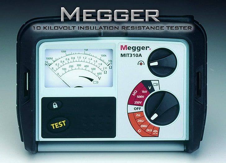
Selection of IR Testers (Megger):
Insulation testers with test voltage of 500, 1000, 2500 and 5000 V are available. The recommended ratings of the insulation testers are given below:
| Voltage Level | IR Tester |
| 650V | 500V DC |
| 1.1KV | 1KV DC |
| 3.3KV | 2.5KV DC |
| 66Kv and Above | 5KV DC |
Test Voltage for Meggering:
When AC Voltage is used, The Rule of Thumb is:
Test Voltage (A.C) = (2X Name Plate Voltage) +1000.
When DC Voltage is used (Most used in All Megger)
Test Voltage (D.C) = (2X Name Plate Voltage).
| Equipment / Cable Rating | DC Test Voltage |
| 24V To 50V | 50V To 100V |
| 50V To 100V | 100V To 250V |
| 100V To 240V | 250V To 500V |
| 440V To 550V | 500V To 1000V |
| 2400V | 1000V To 2500V |
| 4100V | 1000V To 5000V |
Measurement Range of Megger:
| Test voltage | Measurement Range |
| 250V DC | 0MΩ to 250GΩ |
| 500V DC | 0MΩ to 500GΩ |
| 1KV DC | 0MΩ to 1TΩ |
| 2.5KV DC | 0MΩ to 2.5TΩ |
| 5KV DC | 0MΩ to 5TΩ |
Precaution while Meggering
Before Meggering:
Make sure that all connections in the test circuit are tight. Test the megger before use, whether it gives INFINITY value when not connected, and ZERO when the two terminals are connected together and the handle is rotated.
During Meggering:
Make sure when testing for earth, that the far end of the conductor is not touching, otherwise the test will show faulty insulation when such is not actually the case.
Make sure that the earth used when testing for earth and open circuits is a good one otherwise the test will give wrong information. Spare conductors should not be meggered when other working conductors of the same cable are connected to the respective circuits.
After completion of cable Meggering:
- Ensure that all conductors have been reconnected properly.
- Test the functions of Points, Tracks & Signals connected through the cable for their correct response.
- In case of signals, aspect should be verified personally.
- In case of points, verify positions at site. Check whether any polarity of any feed taken through the cable has got earthed inadvertently.
Safety Requirements for Meggering:
- All equipment under test MUST be disconnected and isolated.
- Equipment should be discharged (shunted or shorted out) for at least as long as the test voltage was applied in order to be absolutely safe for the person conducting the test.
- Never use Megger in an explosive atmosphere.
- Make sure all switches are blocked out and cable ends marked properly for safety.
- Cable ends to be isolated shall be disconnected from the supply and protected from contact to supply, or ground, or accidental contact.
- Erection of safety barriers with warning signs, and an open communication channel between testing personnel.
- Do not megger when humidity is more than 70 %.
- Good Insulation: Megger reading increases first then remain constant.
- Bad Insulation: Megger reading increases first and then decreases.
- Expected IR value gets on Temp. 20 to 30 decree centigrade.
- If above temperature reduces by 10 degree centigrade, IR values will increased by two times.
- If above temperature increased by 70 degree centigrade IR values decreases by 700 times.
How to use Megger
Meggers is equipped with three connection Line Terminal (L), Earth Terminal (E) and Guard Terminal (G).

Resistance is measured between the Line and Earth terminals, where current will travel through coil 1. The “Guard” terminal is provided for special testing situations where one resistance must be isolated from another. Let’s us check one situation where the insulation resistance is to be tested in a two-wire cable.
To measure insulation resistance from a conductor to the outside of the cable, we need to connect the “Line” lead of the megger to one of the conductors and connect the “Earth” lead of the megger to a wire wrapped around the sheath of the cable.

In this configuration the Megger should read the resistance between one conductor and the outside sheath.
We want to measure Resistance between Conductor- 2 to sheaths but actually megger measure resistance in parallel with the series combination of conductor-to-conductor resistance (Rc1-c2) and the first conductor to the sheath (Rc1-s).
If we don’t care about this fact, we can proceed with the test as configured. If we desire to measure only the resistance between the second conductor and the sheath (Rc2-s), then we need to use the megger’s “Guard” terminal.

Connecting the “Guard” terminal to the first conductor places the two conductors at almost equal potential.
With little or no voltage between them, the insulation resistance is nearly infinite, and thus there will be no current between the two conductors. Consequently, the Megger’s resistance indication will be based exclusively on the current through the second conductor’s insulation, through the cable sheath, and to the wire wrapped around, not the current leaking through the first conductor’s insulation.
The guard terminal (if fitted) acts as a shunt to remove the connected element from the measurement. In other words, it allows you to be selective in evaluating certain specific components in a large piece of electrical equipment. For example consider a two core cable with a sheath.
As the diagram below shows there are three resistances to be considered.

If we measure between core B and sheath without a connection to the guard terminal some current will pass from B to A and from A to the sheath. Our measurement would be low. By connecting the guard terminal to A the two cable cores will be at very nearly the same potential and thus the shunting effect is eliminated.
Continued here – Measurement of insulation resistance (IR) – Part 2


During Insulation testing we apply through megger AC voltage or DC voltage ?
iF DC voltage that how to check insulation resistance in AC cable / AC motor please certify.
IR(insulation test)
Meggaring depand of the voltage
Ex- 600sq cable rating voltage- 6 to 11 Kv
You inject the DC volt 5Kv
Useless data.
24V min insulation resistance value is not depicted whereas equipment / cable rating test voltage is shown for it.
Measurement range of megger display should be least concerned.
When someone looks at this type of articles he wants to know what should be the acceptable value for a voltage.
Dear sir.
I want to know how to conected transformer Y-Y to polarity index (PI),
I am student electrical engineering.
For please
Request indicate minimum Insulation resistance(IR) required when multiple systems connected to common switch board. The IR meter fitted in main switch board with main bus bar.
Dear Sir,
Could you kindly confirm the below info you provided
250V DC 0MΩ to 250GΩ
500V DC 0MΩ to 500GΩ
1KV DC 0MΩ to 1TΩ
To my understanding, see below
250VDC shall be 0 ohm to 250 KiloOhm
500 VDC shall be 0 ohm to 500 KiloOhm
1000VDC shall be o ohm to 1MOhm
2.5KVDC 0Ω to 2.5MΩ
5KVDC 0Ω to 5MΩ
Correct me if i am wrong
No u r assumption is Wrong Actually IR Checks will be Shown in Megaohms and Above So If You have a megger check it
appreciated explanation
I am an electrician working on small boats at 12 and 24 VDC; also at 120 and 240 VAC IN miami florida with temperatures 20 to 37 C, and humidity 80 to above 100%; cables are sometime submerged in fresh or sea water, and sometimes diesel fuel, not to mention how delicate are electronic navigation equipment.
Tough conditions for such short cables under 10 mts long.
Cable is properly specified for water, salt and oil condition, additionally is thin stranded and tin plated; but expectedshir life is well known in the industry.
Specially when ends are not well sealed with heat shrink sleeves…..
I am thinking in adding dielectric silicone seal before hot drinking sleeves… but heat and silicone….
And definitely I wouldn’t use a Megger on boats powered with gasoline engine’s.
Mainly I replace cables by appearance, visual inspection ofbendsvandbthr plastic insulation flexibility and stained surfaces.
Are you aware of a sensitive megger for short thinn cable or for classified areas?
Thus IR testing subject is very helpful for us electrical practitioners. Thanks a lot.
Regarding polarization index test in which electrical equipment we can applied it.
what about for 3 core cable? how we can use guard?
I want to know ” how much require resistance for 500 V.
If the operating voltage is 500V ,then you will need to use 1000V DC on the Meggar. The test voltage should be roughly two times the operating voltage, with the maximum on the meggar set at 5000V DC for higher operating voltage above 66KV
Solar panel 0- 24v
Please tell me requied testing range of voltage level and test results
hi Jignesh, what about the other end of the cable? We need to make sure cores A and B are insulated from each other and not earthed right?
I have 6.6KV transformer what the is IR DC voltage test should I use
Really appreciate your Effort.
I.R. TESTS ARE ALSO BEING PERFORMED AS PRE-REQUISITE MUST DURING PRE-COMM. AND COMMISSIONING PRIOR TO POWER-UP OR ENERGIZATION OF ALL THE LV AND MV AND HV ELECTRICAL POWER CABLES FEEDING THE EQUIPMENT IT SERVES, AT DIFFERENT TEST VOLTAGES INPUT.
Why is IR Value decreasing after AC high voltage test?
What is the dc voltage to applied for 3.3 kV switchgear for IR Test?
great sir.
my qstn is how a electricity synchonise with the frequency from grid to our cpp.
what are the symptoms.
regards.
if WE PROVIDE ACCESS VOLTAGES VIA MAGGER LIKE A CABLE WHICH IS USED FOR 400V. WE CAN GIVE JUST 500V but what happen if we give 1000V ?
Please i want simple diagram of how to test insulation resistance between two single core pvc insulated cable. Thank you.
Sir,
I’m going to measure the insulation resistance in 132kv line, what should be the required value of phase R- y, R-B, n Y-B & Earth resistance of R- Earth, Y- Earth n B- earth ?
Please i want simple diagram of how to test insulation resistance between conductors. Thank you.
Sir I want know what is the voltage drop for the following 11KV cable.
Considering 3 core 70Cq mm XLPE cable;
Cable resistance and Resistance per KM = 0.164 + j 0.082
Length of cable, = 2.5 Km.
Current carried —– ?
Full Load Transformer = 500KVA
Usage Current Amperes 200 Amperes
1.what is the safe value ,if i am test LT cable / equipments .
2.Any counting restriction (No. of times meggered)
Why is it that the IR value of 66 KV line is differnt when measured with 2.5 KV, 5 KV, 10 KV meggers
Looking forward to read next article!