
Estimated Study Time: 25 minutes
Insulation Resistance (IR)
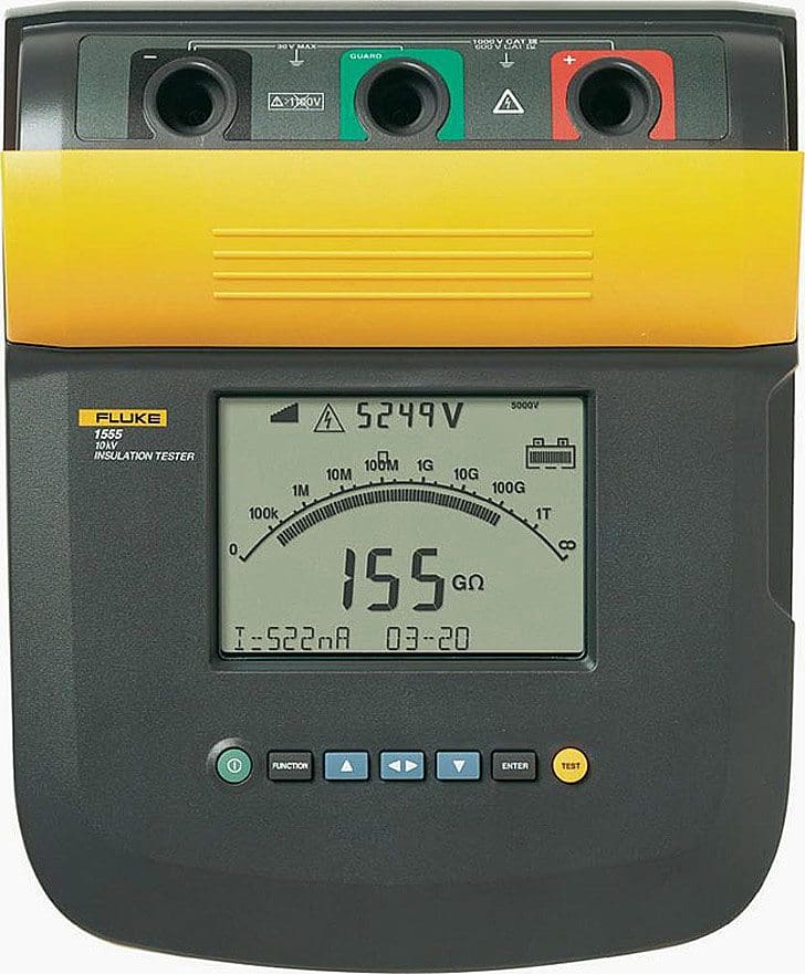
This article goes into details of insulation resistance values measured by Megger tester on many different kinds of equipment, such as switchgear, electrical wires & cables, electric motors, transmission & distribution lines, and other power system equipment. An insulation tester is a portable device that gives a direct measurement of insulation resistance in ohms, megohms, gigohms, or teraohms, irrespective of the chosen test voltage.
Good insulation typically shows resistance measurements in the megohm range or greater. An insulation tester is fundamentally a high-resistance meter (ohmmeter) equipped with an integrated DC generator.
This technical article is continued from first part: Measurement of insulation resistance (IR) – Part 1. I recommend studying the first part before going into this part.
Insulation Resistance (IR) Values – Index
- IR Values For Electrical Apparatus & Systems
- IR Value for Transformer
- IR Value for Tap Changer
- IR Value for Electric motor
- IR Value for Electrical cable and wiring
- IR Value for Transmission / Distribution Line
- IR Value for Panel Bus
- IR Value for Substation Equipment
- IR Value for Domestic /Industrial Wiring
- Required Precautions
1. IR Values For Electrical Apparatus & Systems
(PEARL Standard / NETA MTS-1997 Table 10.1)
| Max.Voltage Rating Of Equipment | Megger Size | Min.IR Value |
| 250 Volts | 500 Volts | 25 MΩ |
| 600 Volts | 1,000 Volts | 100 MΩ |
| 5 KV | 2,500 Volts | 1,000 MΩ |
| 8 KV | 2,500 Volts | 2,000 MΩ |
| 15 KV | 2,500 Volts | 5,000 MΩ |
| 25 KV | 5,000 Volts | 20,000 MΩ |
| 35 KV | 15,000 Volts | 100,000 MΩ |
| 46 KV | 15,000 Volts | 100,000 MΩ |
| 69 KV | 15,000 Volts | 100,000 MΩ |
One Meg ohm Rule for IR Value for Equipment
Based upon equipment rating:
< 1K V = 1 MΩ minimum
>1KV = 1 MΩ /1KV
As per IE Rules-1956:
At a pressure of 1000 V applied between each live conductor and earth for a period of one minute the insulation resistance of HV installations shall be at least 1 Mega ohm or as specified by the Bureau of Indian Standards.
Medium and Low Voltage Installations- At a pressure of 500 V applied between each live conductor and earth for a period of one minute, the insulation resistance of medium and low voltage installations shall be at least 1 Mega ohm or as specified by the Bureau of Indian Standards] from time to time.
As per CBIP specifications the acceptable values are 2 Mega ohms per KV
2. IR Value for Transformer
Insulation resistance tests are made to determine insulation resistance from individual windings to ground or between individual windings. Insulation resistance tests are commonly measured directly in megohms or may be calculated from measurements of applied voltage and leakage current.
The recommended practice in measuring insulation resistance is to always ground the tank (and the core). Short circuit each winding of the transformer at the bushing terminals. Resistance measurements are then made between each winding and all other windings grounded.
Figure 1 – Insulation resistance testing: HV – Earth and HV – LV

Transformer windings are never left floating for insulation resistance measurements. Solidly grounded winding must have the ground removed in order to measure the insulation resistance of the winding grounded. If the ground cannot be removed, as in the case of some windings with solidly grounded neutrals, the insulation resistance of the winding cannot be measured. Treat it as part of the grounded section of the circuit.
We need to test winding to winding and winding to ground ( E ).For three phase transformers, We need to test winding ( L1,L2,L3 ) with substitute Earthing for Delta transformer or winding ( L1,L2,L3 ) with earthing ( E ) and neutral ( N ) for wye transformers.
| IR Value for Transformer (Ref: A Guide to Transformer Maintenance by. JJ. Kelly. S.D Myer) | |
| Transformer | Formula |
| 1 Phase Transformer | IR Value (MΩ) = C X E / (√KVA) |
| 3 Phase Transformer (Star) | IR Value (MΩ) = C X E (P-n) / (√KVA) |
| 3 Phase Transformer (Delta) | IR Value (MΩ) = C X E (P-P) / (√KVA) |
| Where C= 1.5 for Oil filled T/C with Oil Tank, 30 for Oil filled T/C without Oil Tank or Dry Type T/C. | |
Temperature correction Factor (Base 20°C):
| Temperature correction Factor | ||
| °C | °F | Correction Factor |
| 0 | 32 | 0.25 |
| 5 | 41 | 0.36 |
| 10 | 50 | 0.50 |
| 15 | 59 | 0.720 |
| 20 | 68 | 1.00 |
| 30 | 86 | 1.98 |
| 40 | 104 | 3.95 |
| 50 | 122 | 7.85 |
Example: For 1600KVA, 20KV/400V,Three Phase Transformer
- IR Value at HV Side= (1.5 x 20000) / √ 1600 = 16000 / 40 = 750 MΩ at 20°C
- IR Value at LV Side = (1.5 x 400 ) / √ 1600 = 320 / 40 = 15 MΩ at 20°C
- IR Value at 30°C = 15×1.98 = 29.7 MΩ
Insulation Resistance of Transformer Coil
| Transformer Coil Voltage | Megger Size | Min.IR Value Liquid Filled T/C | Min.IR Value Dry Type T/C |
| 0 – 600 V | 1KV | 100 MΩ | 500 MΩ |
| 600 V To 5KV | 2.5KV | 1,000 MΩ | 5,000 MΩ |
| 5KV To 15KV | 5KV | 5,000 MΩ | 25,000 MΩ |
| 15KV To 69KV | 5KV | 10,000 MΩ | 50,000 MΩ |
IR Value of Transformers
| Voltage | Test Voltage (DC) LV side | Test Voltage (DC) HV side | Min IR Value |
| 415V | 500V | 2.5KV | 100MΩ |
| Up to 6.6KV | 500V | 2.5KV | 200MΩ |
| 6.6KV to 11KV | 500V | 2.5KV | 400MΩ |
| 11KV to 33KV | 1000V | 5KV | 500MΩ |
| 33KV to 66KV | 1000V | 5KV | 600MΩ |
| 66KV to 132KV | 1000V | 5KV | 600MΩ |
| 132KV to 220KV | 1000V | 5KV | 650MΩ |
Steps for measuring the IR of Transformer:
- Shut down the transformer and disconnect the jumpers and lightning arrestors.
- Discharge the winding capacitance.
- Thoroughly clean all bushings
- Short circuit the windings.
- Guard the terminals to eliminate surface leakage over terminal bushings.
- Record the temperature.
- Connect the test leads (avoid joints).
- Apply the test voltage and note the reading. The IR. Value at 60 seconds after application of the test voltage is referred to as the Insulation Resistance of the transformer at the test temperature.
- The transformer Neutral bushing is to be disconnected from earth during the test.
- All LV surge diverter earth connections are to be disconnected during the test.
- Due to the inductive characteristics of transformers, the insulation resistance reading shall not be taken until the test current stabilizes.
- Avoid meggering when the transformer is under vacuum.
Test Connections of Transformer for IR Test (Not Less than 200 MΩ)
Two winding transformer
- (HV + LV) – GND
- HV – (LV + GND)
- LV – (HV + GND)
Three winding transformer
- HV – (LV + TV + GND)
- LV – (HV + TV + GND)
- (HV + LV + TV) – GND
- TV – (HV + LV + GND)
Auto transformer (two windings)
- (HV + LV) – GND
Auto Transformer (three winding)
- (HV + LV) – (TV + GND)
- (HV + LV + TV) – GND
- TV – (HV + LV + GND)
For any installation, the insulation resistance measured shall not be less than:
- HV – Earth 200 M Ω
- LV – Earth 100 M Ω
- HV – LV 200 M Ω
Factors affecting on IR value of Transformer
The IR value of transformers are influenced by
- Surface condition of the terminal bushing
- Quality of oil
- Quality of winding insulation
- Temperature of oil
- Duration of application and value of test voltage
Watch Video – Transformer windings basic insulation tests (IR)
3. IR Value for Tap Changer
Winding resistance is measured in the factory to ensure correct manufacture and to determine conductor losses. This measurement is conducted on-site to analyze potential winding damage, including short circuits between windings or turns, open circuits, contact issues, and to check the status of the tap changer.
- IR between HV and LV as well as windings to earth.
- Minimum IR value for Tap changer is 1000 ohm per volt service voltage
Watch Video – Measuring DC winding resistance and checking the tap changer
4. IR Value for Electric motor
For electric motor, we used a insulation tester to measure the resistance of motor winding with earthing (E).
- For rated voltage below 1KV, measured with a 500VDC Megger.
- For rated voltage above 1KV, measured with a 1000VDC Megger.
- In accordance with IEEE 43, clause 9.3, the following formula should be applied.
- Min IR Value (For Rotating Machine) = (Rated voltage (v) /1000) + 1
 value for electric motor")
| As per IEEE 43 Standard 1974, 2000 | |
| IR Value in MΩ | |
| IR (Min) = kV+1 | For most windings made before about 1970, all field windings, and others not described below |
| IR (Min) = 100 MΩ | For most dc armature and ac windings built after about 1970 (form wound coils) |
| IR (Min) = 5 MΩ | For most machines with random -wound stator coils and form-wound coils rated below 1kV |
Example-1: For 11KV, Three Phase Motor.
- IR Value =11+1=12 MΩ but as per IEEE43 It should be 100 MΩ
Example-2: For 415V,Three Phase Motor
- IR Value =0 .415+1=1.41 MΩ but as per IEEE43 It should be 5 MΩ.
- As per IS 732 Min IR Value of Motor = (20×Voltage(p-p/(1000+2XKW)
IR Value of Motor as per NETA ATS 2007. Section 7.15.1
| Motor Name Plate (V) | Test Voltage | Min IR Value |
| 250V | 500V DC | 25 MΩ |
| 600V | 1000V DC | 100MΩ |
| 1000V | 1000V DC | 100MΩ |
| 2500V | 1000V DC | 500MΩ |
| 5000V | 2500V DC | 1000MΩ |
| 8000V | 2500V DC | 2000MΩ |
| 15000V | 2500V DC | 5000MΩ |
| 25000V | 5000V DC | 20000MΩ |
| 34500V | 15000V DC | 100000MΩ |
IR Value of Submersible Motor:
| IR Value of Submersible Motor | |
| Motor Out off Well (Without Cable) | IR Value |
| New Motor | 20 MΩ |
| A used motor which can be reinstalled | 10 MΩ |
| Motor Installed in Well (With Cable) | |
| New Motor | 2 MΩ |
| A used motor which can be reinstalled | 0.5 MΩ |
Watch Video – “Megger” insulation test on a bad motor
5. IR Value for Electrical cable and wiring
For insulation testing, we need to disconnect from panel or equipment and keep them isolated from power supply. The wiring and cables need to test for each other ( phase to phase ) with a ground ( E ) cable. The Insulated Power Cable Engineers Association (IPCEA) provides the formula to determine minimum insulation resistance values.
R = K × Log 10 (D/d)
Where:
- R = IR Value in MΩs per 1000 feet (305 meters) of cable.
- K = Insulation material constant. (Varnished Cambric = 2460, Thermoplastic Polyethlene = 50000, Composite Polyethylene = 30000)
- D = Outside diameter of conductor insulation for single conductor wire and cable (D = d + 2c + 2b diameter of single conductor cable)
- d = Diameter of conductor
- c = Thickness of conductor insulation
- b = Thickness of jacket insulation
HV test on new XLPE cable (As per ETSA Standard)
| Application | Test Voltage | Min IR Value |
| New cables – Sheath | 1KV DC | 100 MΩ |
| New cables – Insulation | 10KV DC | 1000 MΩ |
| After repairs – Sheath | 1KV DC | 10 MΩ |
| After repairs – Insulation | 5KV DC | 1000MΩ |
11kV and 33kV Cables between Cores and Earth (As per ETSA Standard)
| Application | Test Voltage | Min IR Value |
| 11KV New cables – Sheath | 5KV DC | 1000 MΩ |
| 11KV After repairs – Sheath | 5KV DC | 100 MΩ |
| 33KV no TF’s connected | 5KV DC | 1000 MΩ |
| 33KV with TF’s connected. | 5KV DC | 15MΩ |

IR Value Measurement (Conductors to conductor (Cross Insulation))
- The first conductor for which cross insulation is being measured shall be connected to Line terminal of the megger. The remaining conductors looped together (with the help of crocodile clips) i. e. Conductor 2 and onwards, are connected to Earth terminal of megger. Conductors at the other end are left free.
- Now rotate the handle of megger or press push button of megger. The reading of meter will show the cross Insulation between conductor 1 and rest of the conductors. Insulation reading shall be recorded.
- Now connect next conductor to Line terminal of the megger & connect the remaining conductors to earth terminal of the megger and take measurements.
IR Value Measurement (Conductor to Earth Insulation)
- Connect conductor under test to the Line terminal of the megger.
- Connect earth terminal of the megger to the earth.
- Rotate the handle of megger or press push button of megger. The reading of meter will show the insulation resistance of the conductors. Insulation reading shall be recorded after applying the test voltage for about a minute till a steady reading is obtained.
IR Value Measurements:
- If during periodical testing, insulation resistance of cable is found between 5 and 1 MΩ /km at buried temperature, the subject cable should be programmed for replacement.
- If insulation resistance of the cable is found between 1000 and 100 KΩ /km, at buried temperature, the subject cable should be replaced urgently within a year.
- If the insulation resistance of the cable is found less than 100 kilo ohm/km., the subject cable must be replaced immediately on emergency basis.
Watch Video – Field Insulation Test
Comment: I started by making sure the conductors to be tested were clear at the other end of the circuit. I also terminated the equipment ground conductors at the other end of the circuit and verified I had a path to ground via an ohm test from those grounds to a nearby footer steel connection which turned out to be .4 ohms. There is a lot of grounded steel on this project so this was a good reading to have. I ran the test on all conductors and they all tested out at 2.4 megohms and higher. I needed to see a minimum of 1 megohm so this gave all conductors a passing grade. Sorry about the background noise, these jobs are noisy!
6. IR Value for Transmission Line / Distribution Line
| Equipment | Megger Size | Min IR Value |
| S/S .Equipments | 5 KV | 5000MΩ |
| EHVLines. | 5 KV | 10MΩ |
| H.T. Lines. | 1 KV | 5MΩ |
| LT / Service Lines. | 0.5 KV | 5MΩ |
7. IR Value for Panel Bus
IR Value for Panel = 2 x KV rating of the panel.
Example, for a 5 KV panel, the minimum insulation is 2 x 5 = 10 MΩ.
8. IR Value for Substation Equipment
Generally meggering Values of Substation Equipments are.
| Typical IR Value of S/S Equipments | |||
| Equipment | Megger Size | IR Value(Min) | |
| Circuit Breaker | (Phase-Earth) | 5KV,10 KV | 1000 MΩ |
| (Phase-Phase) | 5KV,10 KV | 1000 MΩ | |
Control Circuit | 0.5KV | 50 MΩ | |
CT/PT | (Pri-Earth) | 5KV,10 KV | 1000 MΩ |
| (Sec-Phase) | 5KV,10 KV | 50 MΩ | |
| Control Circuit | 0.5KV | 50 MΩ | |
| Isolator | (Phase-Earth) | 5KV,10 KV | 1000 MΩ |
| (Phase-Phase) | 5KV,10 KV | 1000 MΩ | |
| Control Circuit | 0.5KV | 50 MΩ | |
| L.A | (Phase-Earth) | 5KV,10 KV | 1000 MΩ |
| Electrical Motor | (Phase-Earth) | 0.5KV | 50 MΩ |
| LT Switchgear | (Phase-Earth) | 0.5KV | 100 MΩ |
| LT Transformer | (Phase-Earth) | 0.5KV | 100 MΩ |
| IR Value of S/S Equipments As per DEP Standard | |||
| Equipment | Meggering | IR Value at Commissioning Time (MΩ) | IR Value at Maintenance Time |
| Switchgear | HV Bus | 200 MΩ | 100 MΩ |
| LV Bus | 20 MΩ | 10 MΩ | |
| LV wiring | 5 MΩ | 0.5 MΩ | |
| Cable(min 100 Meter) | HV & LV | (10XKV) / KM | (KV) / KM |
| Motor & Generator | Phase-Earth | 10(KV+1) | 2(KV+1) |
| Transformer Oil immersed | HV & LV | 75 MΩ | 30 MΩ |
| Transformer Dry Type | HV | 100 MΩ | 25 MΩ |
| LV | 10 MΩ | 2 MΩ | |
| Fixed Equipments/Tools | Phase-Earth | 5KΩ / Volt | 1KΩ / Volt |
| Movable Equipments | Phase-Earth | 5 MΩ | 1MΩ |
| Distribution Equipments | Phase-Earth | 5 MΩ | 1MΩ |
| Circuit Breaker | Main Circuit | 2 MΩ / KV | – |
| Control Circuit | 5MΩ | – | |
| Relay | D.C Circuit-Earth | 40MΩ | – |
| LT Circuit-Earth | 50MΩ | – | |
| LT-D.C Circuit | 40MΩ | – | |
| LT-LT | 70MΩ | – | |
9. IR Value for Domestic /Industrial Wiring
A low resistance between phase and neutral conductors, or from live conductors to earth, will result in a leakage current. This cause deterioration of the insulation, as well as involving a waste of energy which would increase the running costs of the installation.
The resistance between Phase-Phase-Neutral-Earth must never be less than 0.5 M Ohms for the usual supply voltages.
In addition to the leakage current due to insulation resistance, there is a further current leakage in the reactance of the insulation, because it acts as the dielectric of a capacitor. This current dissipates no energy and is not harmful, but we wish to measure the resistance of the insulation, so DC Voltage is used to prevent reactance from being included in the measurement.
1 Phase Wiring
>The IR test between Phase-Natural to earth must be carried out on the complete installation with the main switch off, with phase and neutral connected together, with lamps and other equipment disconnected, but with fuses in, circuit breakers closed and all circuit switches closed.
Where two-way switching is wired, only one of the two stripper wires will be tested. To test the other, both two-way switches should be operated and the system retested. If desired, the installation can be tested as a whole, when a value of at least 0.5 M Ohms should be achieved.

3 Phase Wiring
In the case of a very large installation where there are many earth paths in parallel, the reading would be expected to be lower. If this happens, the installation should be subdivided and retested, when each part must meet the minimum requirement.

The IR tests must be carried out between Phase-Phase-Neutral-Earth with a minimum acceptable value for each test of 0.5 M Ohms.
| IR Testing for Low voltage | ||
| Circuit voltage | Test voltage | IR Value(Min) |
| Extra Low Voltage | 250V DC | 0.25MΩ |
| Up to 500 V except for above | 500 V DC | 0.5MΩ |
| 500 V To 1KV | 1000 V DC | 1.0MΩ |
Min IR Value = 50 MΩ / No of Electrical outlet. (All Electrical Points with fitting & Plugs)
Min IR Value = 100 MΩ / No of Electrical outlet. (All Electrical Points without fitting & Plugs).
Required Precautions
Electronic equipment like electronic fluorescent starter switches, touch switches, dimmer switches, power controllers, delay timers could be damaged by the application of the high test voltage should be disconnected.
Capacitors and indicator or pilot lamps must be disconnected or an inaccurate test reading will result.
Where any equipment is disconnected for testing purposes, it must be subjected to its own insulation test, using a voltage which is not likely to result in damage. The result must conform with that specified in the British Standard concerned, or be at least 0.5 M Ohms if there is no Standard.
Bad Effects of Temperature
Temperature fluctuations can substantially impact insulation resistance measurements. Resistance significantly decreases with a rise in temperature for the same equipment. Every kind of insulating material has a distinct variation in resistance in response to temperature changes.
Manufacturers provide temperature correction factor charts for different types of electrical devices. If that is not feasible, it is advisable to create your own correction factor tables by documenting two resistance readings for the same equipment at two distinct temperatures. A graph can be created with resistance plotted on a logarithmic scale and temperature on a linear scale.
The graph is linear and may be extrapolated to any temperature, allowing for direct reading of correction factors.
Bad Effects of Humidity
Humidity (moisture content) influences insulation resistance; however, its impact cannot be as precisely calculated as that of temperature, due to the differing moisture absorption rates of various insulation kinds, as well as the changing ages and conditions of identical types. Humidity is a significant component that must not be disregarded when assessing test findings.
In contrast to temperature, the influence of humidity is not a uniform gradient; if the temperature stays above the dew point, humidity will not significantly impact insulating measurements.
In electrical apparatus, our primary concern is the circumstances on the exposed surfaces where moisture condenses, impacting the overall resistance of the insulation. Research indicates that dew accumulates in the fissures and recesses of insulation prior to becoming visibly apparent on the surface. Dew-point readings will indicate the potential existence of unseen circumstances that may affect the test outcomes.
Related electrical guides & articles


Jignesh Parmar
Electrical Middle management professional having more than 22 years rich and dynamic experience in Project Execution / Project Management / Designing / Maintenance diversifies from Electrical Power Transmission (400KV/220KV/66KV)- Distribution(11KV/220V) to Lifts-HVAC-Ventilation-Fire Fighting-Fire Alarm-Lifts-CCTV-Stack Parking Works (High Rise Buildings, Townships, Shopping Complex, Commercial Complex, School, Temple).Profile: Jignesh Parmar

What is TI2 insulation?..and how you read its unit of MΩ Km?..thank you.
What is the minimum require insulation resistance for a furnace transformer rated to 50MVA, 27.6 KV/ 600V.
Ambient temperature is 25 degree C
hello
Would you please explain the difference between Mohm/Km & Mohm.Km for insulation resistance of the cables especially
Please advice the best value must be applied during test the insulation resistance of power supply cord with plug (F) length 1.6 meter .
Thanks / Nabil Aziz
Can we use 5Kv IR tester for a 250 v domestic wiring?
May i know how, must be the insulation resistance of a generator 681 kva, we are operaing at 3 phase 400 v line to line .we send our generator for repair/ rewind so that we have a base standard requirement for the IR of our generator.
Hello.
In which Standards can we find the IR Value for Transmission / Distribution Line?
Thank you in advance.
Hello,
Advise on the recommended Insulation Resistance Value for a new a) 25kv Flexible Overhead Catenary System (Catenary 65sqmm strandeed Cu + Contact-150sqmm Hard drawn Cu) support on steel strcuture and cantilever with 25kv Insulator on Open air (Railway/Metro System) b) Rigid Conductor Rail bar with Hard drawn 150sqmm Cu. This is because while conducting the tests the IR value is as low as 15 Mega Ohms. Is it objectionable as per Standards to 25kv Charge the line?
JUST TO THANK JIGNEH P. FOR SHEARING HIS KNOWLEDGE
Dear sir/ madam,
Low Voltage Motor 5.5kw 400vac.How much is the standard Megger value.
I got 800 M-OMG when I tested a new cable by the following details:
1. 11 kv
2. 12 km
3. 22 nos of joint
I need to knew why it is came less the 1G-OMG
Neutral & Sectioned Insulator Rate of 25 kv, 1600 Amp Single Pole
Kindly suggest, machine operating voltage is 11 KV , for IR value improvement purpose heating process done. Can i measure Megger test at 90- 100 Deg Celsius .
Good knowledge for site works.
Is there any formula to calculate insulation resistance for cables with respect to temperature?
When testing IR for transformer, what is the difference between Insulation Resistance of Transformer Coil and IR Value of Transformers ?
Permissible IR Value of 132,33,11 KV Transf,C.T, P.T.&Breaker Meggered by 5 KV.
Dear Sir,
I need IR Test Acceptance Value of 630 Sq.mm single-core armoured cable Cu.Pvc/Pvc.
i need 95sq mm LT UG CABLE insulation valve
why ct pt isolate or disconnectec durring generator meggering
Hi Mr. Jiguparmar,
Could you please advise as follow :
1. How to measure IR OHTL 500KV (line to line and line to earth). Transmission length 52Km. Conductor per phase ACSR quadruple 4 x ACSR Zebra. Is it sufficient 5KV megger or have to use bigger scale such as 20KV?
2. Is it possible to measure IR transmission line 52Km or have to be divided a few segment?
3. What is the IEEE, IEC, BS or NETA standard regarding IR test OHTL EHV?
Thank you so much for your help.
Cheers,
Jonson
Good article.
From where I can get the ETSA standard?
Very useful article
Super information
Sir, is it must to disconnect diodes & AVR of an alternator 450V 1.5 MW prior measuring IR value. I have seen in Europe, IR measured with diode & AVR connected. Because AVR out put can be upto 500AC. Meggar out put is 500VDC.
IR measured without disconnection of diode & AVR to be added to MY previous comment.
dear sir
please send me this pdf file and help me how to download this file
as the temp increases, the insulation strength decreases. For every 10 degree increase, as a rule of thumb, megger value should be halved.
What is the normal heating temperature for generator to read 2.0 PI?
How long does it take to heat the generator to reach the temperature level where we can be able to test IR and get PI value of between 1.5 to 2.5?
Is it possible to measure the IR and get accurate value for PI of 2.0 at high temperature?
Please can you help me to know the maximiumvalue of How do I get out of 3 phase 415 VOLT IR Megger Test in mega OHMS value?
cable size copper 4 core 70 mm@ distance 30mtr.room temp.28-30C
HT isolator 22 KV during off condtion megger value is 2000M ohm but in ON condition megger value is zero. Why?
Check to connected load
Hi…
Great it is,
I have aquestion:
I have spare LT panel (operating voltage-420VAC) and I have to use it somewhere in my factory, but when I am checking its pahse to earth IR value with 1000V IR tester, then it is showing 20 MOhms, is it sufficient to use the panel.
10 hp 3 phase indication motor how to check resistance
Very Useful article. I need an information regarding this.
Why IR testing is done for 1 minute? Is it a standard procedure which is followed everywhere or any technical logic behind it ??
Always you should wait at least 1m.
hi and happy to join you !
i want just to confirm if someone can confirm that IR test can stress the cable in case that testesting requeted every 6 weeks.
What are standards or practices to consider K-Factor (Absorption Coefficient) and Polarization Index (P.I) specially in respect of EHV Power Transformers (viz 220 KV/ 11 KV)
Dear Sir,
I need to know the HV and Megger test voltage value and routine tests to be performed for medium voltage 6.6KV cables.
Please email me to my email.
Regards
Jeevan Ranadive
how frequently should we measure the Insulation resistance value in a motor under service
Very useful article.
Dear Sir
Thanks for all this good work that you have done. I just have doubt that one of the examples of insulation temperature correction factors is given with a probable mistake from the point I looked to the insulator.
If an Insulator measures 15 MOhms @ 20C then it must measure less at 30C. The example you stated mention some thing in contrary (See Below).
Example: For 1600KVA, 20KV/400V,Three Phase Transformer
IR Value at HV Side= (1.5 x 20000) / √ 1600 =16000 / 40 = 750 MΩ at 200C
IR Value at LV Side = (1.5 x 400 ) / √ 1600= 320 / 40 = 15 MΩ at 200C
IR Value at 300C =15X1.98= 29.7 MΩ
For the 22 KV cable (3 cores x 300 sq.mm) :
1- How to Indicate/Define the minimum pass/criteria value, for the Megger (IR) test?
2- How to Indicate/Define the minimum pass/criteria value and define the test voltage, for the outer sheath test ?
thanks for valuable information
To whomever this may concern, whilst the information contained on this website is useful, it is no substitute for the application of competent electrical engineering by experienced practitioners. Electrical engineering practitioners should always read and understand the appropriate guidance, incorrect information is misleading. The primary source of information is described within IEEE, IEC or national standards which must be reviewed before embarking upon electrical engineering works or projects.I wish to thank the author for making this information available to the general public who could be harmed as a consequence. A little knowledge is dangerous.
Sir,one 40MVA Transformer which was in service for 3 years.later moved to 300kms and filteration of oil started.After 30 Days Filteration the IR value of LV to earth is 10 Mega ohms.what is the reason for such low value?
Which Indian Standard is for Electric Insulation resistance measurement/Testing & Evaluate the reading as either acceptable or not. Value below which Insulation is not acceptable etc
Excellent work on single paper.
Thank you for this very useful article.
Is there any IR lower-limit for turn-to-turn insulation in random wound (low voltage) electric motors?
Thank you,
VM
Why to avoid meggering when the transformer is under vacuum?
An electrician performed Insulation Resistance test on Low Voltage cable between a Generator and switchboard. Due to site constraints the cable could not be disconnected at both ends of the installation, however the circuit breakers were switched off at both ends leaving the neutral and earth connected. Do you think the neutral and earth cable needs to be disconnected or can remain and we measure the IR value between Phase and Neutral/earth.
Sir, it has been observed that during oil replacement procedure of a power transformer in one of our Substations IR values were taken after draining of oil and after filling with oil. It was found that the reading was less with oil than without oil. What is the reason?
sorry I’m a little bit confused…what formula should I use for IR testing of motor is it
Min IR Value (For Rotating Machine) =(Rated voltage (v) /1000) + 1
or
As per IS 732 Min IR Value of Motor=(20XVoltage(p-p/(1000+2XKW)
How to check d IR value of 765 kv polymer insulator??
What should b d megger range n what is d value ??
Value for LT to Earth is coming only 43M-ohm, any one can give me solution
This is very useful
Thanks for your article. I sent your link to one of overhead crane supplier which was located in some part in Europe, because we were requesting for the IR but they say they do not know such IR. Luckily after searching in the web your article showed up.
Again thank you.
Sir, do you know how to compute the minimum recommended value for busbar?
thanks for the valuable tips about insulation resistance and its importance.. ..
again thanks…
can u plz tell me what will be the practical connection diagram by utilizing the theory given by ur article for transformer insulation resistance measurement such as
Test Connections of Transformer for IR Test (Not Less than 200 MΩ)
Two winding transformer
1. (HV + LV) – GND
2. HV – (LV + GND)
3. LV – (HV + GND)
Three winding transformer
1. HV – (LV + TV + GND)
2. LV – (HV + TV + GND)
3. (HV + LV + TV) – GND
4. TV – (HV + LV + GND)
Auto transformer (two windings)
1. (HV + LV) – GND
Auto Transformer (three winding)
1. (HV + LV) – (TV + GND)
2. (HV + LV + TV) – GND
3. TV – (HV + LV + GND)
and is the meaning of TV ; plz rely it as it is very urgent
I think is tertiary winding
how to calculate lekage current of hv test
exmp.
i have given power frequency 70kv for vcb panel and this vcb ir value coming 123684 ph to earth and phase to phase 254637megaohum
an 11 kw AHU motor how much ohms it should have with body earth .
Very Informative Article.
really very useful
thank you for sharing good information. Keep it up.
GREAT SITE FOR ALL ELECTRICAL INDUSTRY PERSONNEL. BUG UP!
Thank u so much sir…..
Useful guide.thanks
Excelente información, gracias
INDEED, THIS IS A GOOD REFERENCE FOR ALL ELECTRICAL ENGINEERS, PRACTICING OR NOT. AND FOR ENGINEERING STUDENTS, TOO.
any one tell me about insulation measurement by using Impulse tester and Tan Delta Tester.
kindly help me to complete my project.
my email id : [email protected]
What voltage do u use 5 test a 400v bus bar and what are the expected results.
1. How to perform meggering of a 33/11kv outdoor transformer . What are the permissible IR values for, HV-LV, HV-Earth, & LV-Earth while using digital megger at 5kv.
2. What is the “normal and maximum” oil & winding temp allowed on 10MVA(33/11kv) transformer ? Its urgent, Plz help
the transformer to megger is 10MVA(33/11KV)
Please can you help me to know the maximium fire resistance temperture for the follow fire cable with following specifiction:
2×1.5mm2
Aluminum mylar 7*0.18mm
conductor diameter 2.8-3.1mm
Resistance less than 13.3 ohm/km
operationg temperature -20C – +85C
impedence 115 ohm
test voltage 1500V
Isolation resistance more than 10 000 ohm/km
weight per 100m 7.3kg
load up the cable thill it cats fire and then dial the load back a bit and you should ok
useful for me.Thanks
useful for me.Thanks
Dear All,
Megger Value of HV 6.6kV 2 MW Motor after No Load Run (4 Hours Running) are coming Low compared to Before No Load Run Reading of Motor IR??
This is happening for both different motors with ideal rating.
Can any one explain the Reason???
Regards,
T.D.
please ensure the values are corrected for standard temperature. ( i.e – 20 degree Celsius). Definitely there will be a temperature rise of 10 degree Celsius from cold to No-load running.
before motor running stator and winding cold condition that time test leakage current more reading showing low resistance. because temperature factor after some hours running the motor current flow to the winding and resistance varying stator heat up and all moisture out of from motor. stop motor after test showing high resistance value because leakage current less.
A Very Useful Article
Request to mentioned the source of the information provided
THANKS ,GOOD WORK …i LUV this siteeee
Very useful article , I appreciate your efferots to collect all these indexes and values in one paper
Thank you….