
Estimated Study Time: 17 minutes
VSDs and electrical interference
Often referred to as Variable Frequency Drives, AC Variable Speed Drives (VSD) generate a great deal of electrical interference. Pulse Width Modulation (PWM) is the standard method for controlling motor speed in VSDs. The quick rise and fall times of the signals utilized by PWM control circuits might lead to electrical interference as a result of PWM’s operating characteristics.
 Measures to reduce interference from Variable Speed Drives
Electric motor components, VSDs, and control systems are all susceptible to this interference, which can compromise their reliable operation. Motor bearing and stator winding failures, power cable failures, and high frequency electrical interference on control systems are some of the well-documented VSD and motor difficulties found in technical papers.
There have been reports of reflecting wave problems and common mode electrical noise with several VSD brands. Following the manufacturer’s installation guidelines can help avoid concerns linked to electrical interference, according to VSD makers.
- Measures to Reduce VSD Interference:
- Examples of Electrical Noise
- Ground Considerations
- Motor Ground Connections
- VSD Cable Specifications
- Critical Cable Lengths
- BONUS (PDF) 🔗 Download Guide to Power Quality Analysis of Variable Speed Drives
1. Measures to Reduce VSD Interference
Measures to reduce interference from Variable Speed Drives (VSDs) encompass:
- Shorten the Lengths of VSD-Motor Cables
- Apply the Lowest Possible VSD Carrier Frequency
- Use Armored Power Cable
- Use Isolation Transformers for VSD Power
- Use Other Noise Suppression Components
- Use Control-Matched Inverter Duty Motors
Let’s a word about eash measure.
1.1 Shorten the Lengths of VSD-Motor Cables
The quantity of noise that a system generates is heavily dependent on factors like cable type and length. Insulated gate bipolar transistor (IGBT) drives interact with the transmission line due to the rapid rising time of voltage pulses. The possibility of reflected voltages increases as line length increases. For each particular installation, the drive manufacturer should have specified the maximum cable length.
The standard recommendation for cable length is 61 m or less.
1.2 Apply the Lowest Possible VSD Carrier Frequency
How long a cable can be depends on the VSD’s switching (carrier) frequency. The larger the cable’s usable length, the lower the frequency. Electronic components of the drive operate at the drive’s lowest switching frequency.
Electromagnetic interference can exceed frequency of 30 MHz.
Below video demonstrates how adjusting the switching frequency changes the audible noise level.
Watch Video – Effect of Adjusting the Switching Frequency
1.3 Use Armored Power Cable
To protect the system components from high frequency electric fields, the power cables used to connect the VSD to the motor should be protected with a metallic armor, such as copper or aluminum. Additionally, the armour offers a low impedance path back to the AC drive power supply.
Due of steel’s ineffective shielding at higher frequencies, copper or aluminum are better materials to utilize. These findings are the consequence of comprehensive testing of numerous cable kinds.
Look at Table 1.
Table 1 – Cable Shield Properties
| Cable Type | Per Unit Cross Talk | Per Unit Common Mode Current |
| Tray Cable — No shield or Armor (3 grounds) | 56 db | 11.9 db |
| Metal-Clad Type Cable — Aluminum Armor (3 Grounds) | 5.0 db | 1.0 db |
| Metal-Clad Cable — Steel Armor (3 Grounds) | 44 db | 3.9 db |
To protect motors associated with variable speed drives, the most effective cable type is Metal-Clad Type, which has three ground wires arranged symmetrically and a continuous corrugated metal armor. For details, refer to the section on VSD Cable Specifications.
The threaded couplings in aluminum conduit cause corrosion and put the shield’s electrical continuity at risk, so it’s not a good choice.
An all-encompassing foil shield is an option for TC tray cable. It is possible that the foil shield will give sufficient protection, even though it is not as effective as armored wire. In certain cases, the foil shield has served its purpose and greatly reduced the voltage levels of the VSD’s electrical interference, protecting the installation from noise.
Further Study – Seven golden foundations of good electrical installation work
Seven golden foundations of good electrical installation work
1.4 Use Isolation Transformers for VSD Power
An isolation transformer, which is different from the one used for the control system, supplies the VSD with isolated power and a dedicated ground system. A pathway is formed for removing unwanted signals by means of this ground system. In the absence of a ground system, common mode noise is generated when errant signals are directed through the grounds of the main power system.
It is recommended that the windings of the isolation transformer be protected from electrostatic charges.
Further Study – The magic that isolation transformer uses to suppress transients and noise
The magic that isolation transformer uses to suppress transients and noise
1.5 Use Other Noise Suppression Components
Components used in AC drive installations must be designed and tested to comply with EMC standards. In order to reduce electrical noise in VSD applications, it is customary to use input power filters, output power filters, and common mode chokes.
Depending on how much electrical noise gets in the way of the control system’s normal operation, certain noise suppression devices can be necessary.
1.6 Use Control-Matched Inverter Duty Motors
In VSD applications, inverter duty motors are recommended. Motors approved for use with inverters are specifically engineered to endure the increased loads that come with VSD control. When choosing motors for VSD applications, compatibility between the motor and VSD should also be considered.
Using motors that are suitable with the application and the VSD can help reduce motor failures.
Further Study – Ten different duty types (load cycle) of a three-phase asynchronous motor
Ten different duty types (load cycle) of a three-phase asynchronous motor
2. Examples of Electrical Noise
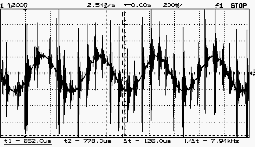
Low power, variable speed drives can create common mode noise on both conventional analog and HART signals, as seen in Figures 1 and 2, which are oscilloscope traces. What seems like noise are big spikes at high frequencies superimposed on otherwise smooth trace lines.
By the way, HART is a bi-directional communication protocol facilitating data access between intelligent field devices and host systems. HART is an shorten for Highway Addressable Remote Transducer.
Figure 1 – Common Mode Noise on an Analog Signal (Display A)
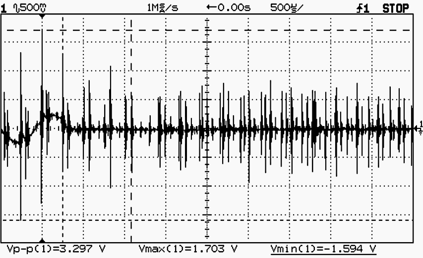
Figure 2 – Common Mode Noise on an Analog Signal (Display B)
3. Ground Considerations
Electrical noise levels are naturally high in VSD drive systems that use IGBT inverters. The rapid rising times (square-wave type signals) in the systems produce high-frequency signals (up to 30 mHz) that are known as noise. A capacitive coupling occurs between the power cable and the motor and the metal in the nearby areas, whereas a magnetic coupling occurs between ground conductors and the field instrumentation and its wiring in close proximity.
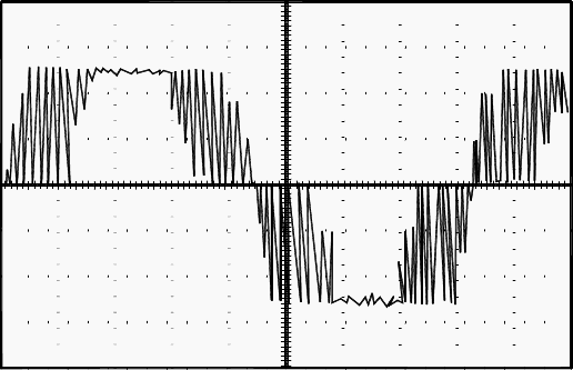
With noise superimposed, Figure 3 shows a typical inverter voltage output. Noise levels at the motor terminals and along the power line are conditional on a number of variables, including the length of the cable.
While each manufacturer’s waveform may look slightly different, all IGBT drives feature rapid rising times and corresponding noise.
Figure 3 – Voltage Output Inverter Signal with Superimposed Noise
If not properly managed, high-frequency noise can lead to motor stator winding failure due to arcing, motor bearing failure from metal transfer, and disrupted control system functionality from directly linked noise and stray ground currents.
To mitigate the impact of noise, the following is imperative:
- Utilize an armored power cord with connections at both terminals. Typically, shielding is grounded at a single end; however, with VSD drives, all internal cable shields and the armor shield must be grounded at both ends.
- Utilize the minimal length of power cable feasible.
- Utilize motors equipped with shielded stator windings.
- Maintain VSD ground cables in close proximity to building steel to mitigate high-frequency signal emission.
- Ensure that the building grounding system offers a low impedance return pathway to genuine earth ground, often your facility’s ground grid.
Figure 4 depicts the power and ground cabling for VSD systems, which, when correctly installed, often mitigates electrical noise to sufficiently low levels, hence minimizing motor damage and ensuring unobstructed control system performance.
Figure 4 – Ground Wiring for Adequate Noise Protection with IGBT Inverters
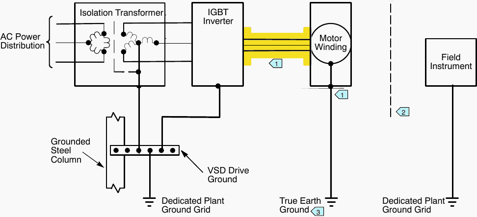
Annotations:
- Refer to Figure 5 for details regarding the ground connection.
- Maintain a considerable distance between field instrumentation and VSD equipment, utilizing armored power cables, insulated motor stator windings, and appropriate grounding to mitigate the impact of stray high-frequency signals.
- The motor frame can be connected to the building’s steel structure if it offers an effective, low-impedance path to a real earth ground, typically a dedicated plant ground grid.
- The waveform is characteristic of high-frequency stray signals that may occur on VSD ground wiring and radiate similarly to radio transmissions.
4. Motor Ground Connections
Figure 5 illustrates the specifications for the grounding connections of the motor power cable. The motor frame is connected to a real earth ground. For new constructions, the frame may be connected to a UFER ground or to adequately grounded building steel. For existing structures, the frame may be grounded to the nearest accessible effectively grounded building steel or grid.
Effectively grounded signifies that the building’s steel offers a low impedance pathway to the real earth ground.
Figure 5 – Ground Connections at Motor Power Cable Ends
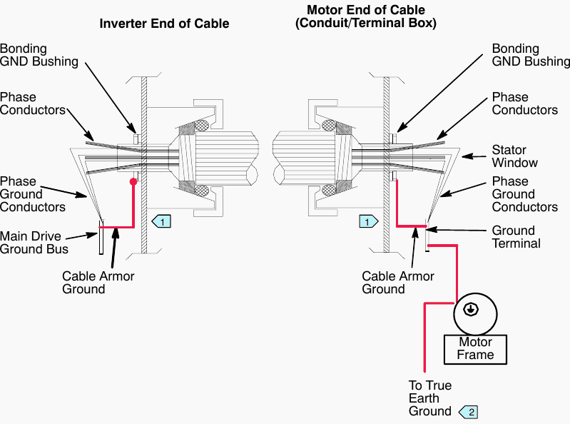
Annotations:
- Cable grounds are terminated at both ends as illustrated.
- The motor frame may be connected to building steel if the steel offers an effective, low-impedance route to a real earth ground, often a dedicated plant ground grid.
Figure 6 illustrates the dropout pathway from the cable tray to the motor.
Figure 6 – Dropouts from Cable Tray to VSD Motor
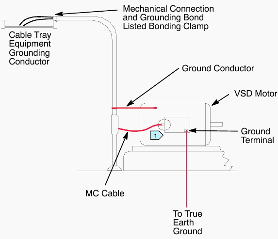
Annotations:
- Refer to Figure 5 for details regarding the ground connection.
5. VSD Cable Specifications
Here are the specs for the VSD cables that are recommended: Table A-2. Many cable manufacturers make VSD cable.
Table 2 – VSD Cable Specifications
| Specification | Description |
| Cable Type | Type MC metal-Clad three-phase cable per NEC 334-1, UL listed |
| Phase Conductors | Three phase-conductors with ampacity per NEC |
| Ground Conductors | Three bare ground conductors per NEC article 250 |
| Metallic Sheath *** | Continuous corrugated aluminum (welded or seamless) |
| Overall Jacket | PVC |
| Voltage Rating | v480 VAC, Cable insulation rating of 600 V AC |
| Connector Type | See Figure 5 |
*** Alternate metallic shields may be copper tape spiral shield with galvanized steel interlocked armor or no shield with aluminum continuous armor.
6. Critical Cable Lengths
The time it takes for the pulse to rise and descend determines the crucial cable length. The shortest distance that won’t cause voltage waves to be reflected at the motor terminals is called the critical length.
Tables 3, 4, and 5 display several criteria for establishing the maximum cable length.
Minimizing reflected voltage waves at motor terminals is influenced by factors such as cable length, switching device, and switching frequency, as shown in the tables below. The terminal voltage can be double the inverter’s output voltage if the cable is sufficiently long.
Table 3 – Critical Cable Lengths by Pulse Rise Time
| Pulse Rise Time | Maximum Cable length |
| 50 nsec | 4 m |
| 100 nsec | 7.6 m |
| 200 nsec | 15 m |
| 400 nsec | 30.5 m |
| 600 nsec | 45 m |
| 1 μsec | 75 m |
| 2 μsec | 180 m |
| 4 μsec | 300 m |
Important Note! Cable lengths greater than 30.5 m are not recommended because of the potential for causing unwanted signals.
Table 4 – Critical Cable Lengths by Switching Type
| Switching Device | Maximum Cable length |
| IGBT 0.1 μsec | 30.5 m |
| Bipolar | 76.2 m |
| GTO 1.0 μsec | 183 m |
| SCR 4.0 μsec | 183 m |
Table 5 – Critical Cable Lengths by Switching Frequency for an IGBT Drive
| Switching Frequency | Maximum Cable length |
| 1 kHz | 61 m |
| 3 kHz | 53.3 m |
| 12 kHz | 30.5 m |
Recommended Course – Practical Course to Wiring and Setting Parameters of Variable Frequency Drives (VFDs)
Acquire the knowledge necessary to wire and configure the parameters of frequency converters for both open and close loop applications. Even if you have no prior experience with frequency converters, you will be able to build a wiring schematic, connect the two components, and put the variable frequency converter into operation.
Ten classes in a total of three hours and eight minutes.
Practical Course to Wiring and Setting Parameters of Variable Frequency Drives (VFDs)
7. BONUS (PDF): A Guide to Power Quality Analysis of Variable Speed Drives (VSDs)
Download Guide: Power Quality Analysis of Variable Speed Drives (for premium members only):
Reference: Control System Power & Grounding by David B., David H., Roger H.
Related electrical guides & articles


Edvard Csanyi
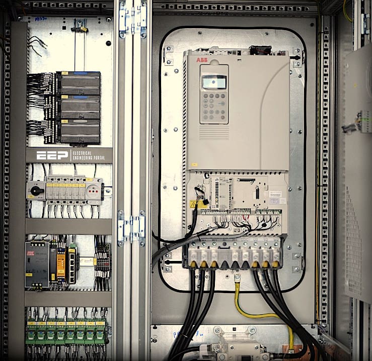
Hi, I'm an electrical engineer, programmer and founder of EEP - Electrical Engineering Portal. I worked twelve years at Schneider Electric in the position of technical support for low- and medium-voltage projects and the design of busbar trunking systems.I'm highly specialized in the design of LV/MV switchgear and low-voltage, high-power busbar trunking (<6300A) in substations, commercial buildings and industry facilities. I'm also a professional in AutoCAD programming.
Profile: Edvard Csanyi
