
Estimated Study Time: 7 minutes
Insulation Resistance Measurement
This test is performed at or above rated voltage to determine if there are low resistance paths to ground or between winding to winding as a result of winding insulation deterioration. The test measurement values are affected by variables such as temperature, humidity, test voltage, and size of transformer.
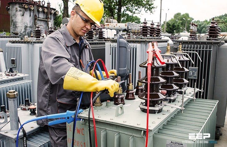 Do's and Don'ts When Measuring Insulation Resistance Of A Transformer (photo credit: sonel.pl)
This test should be conducted before and after repair or when maintenance is performed. The test data should be recorded for future comparative purposes. The test values should be normalized to 20°C for comparison purposes.
The general rule of thumb that is used for acceptable values for safe energization is 1 MΩ per 1000 V of applied test voltage plus 1 MΩ. Sample resistance values of good insulation systems are shown in Table 1.
TABLE 1 – Typical Insulation Resistance Values for Power and Distribution Transformers
| Transformer Winding Voltage (kV) | Winding Ground (MΩ) | ||||
| 22°C | 30°C | 40°C | 50°C | 60°C | |
| 6.6 | 400 | 200 | 100 | 50 | 25 |
| 6.6 – 19 | 800 | 400 | 200 | 100 | 50 |
| 22 – 45 | 1000 | 500 | 250 | 125 | 65 |
| ≥ 66 | 1200 | 600 | 300 | 100 | 75 |
Test procedures:
The test procedures are as follows:
- Do not disconnect the ground connection to the transformer tank and core. Make sure that the transformer tank and core are grounded.
- Disconnect all high voltage, low voltage, and neutral connections, lightning arresters, fan systems, meters, or any low voltage control systems that are connected to the transformer winding.
- Before beginning the test, jumper together all high voltage bushings, making sure that the jumpers are clear of all metal and grounded parts. Also jumper together all low voltage and neutral bushings, making sure jumpers are clear of all metal and grounded parts.
- Use a megohmmeter with a minimum scale of 20,000 MΩ.
- Resistance measurements are then made between each set of windings and ground. The windings that are to be measured must have its ground removed in order to measure its insulation resistance.
- Megohmmeter reading should be maintained for a period of 1 min. Make the following readings for two-winding transformers:
- High-voltage winding to low-voltage winding and to ground
- High-voltage winding to ground
- Low-voltage winding to high-voltage winding and to ground
- Low-voltage winding to ground
- High-voltage winding to low-voltage winding
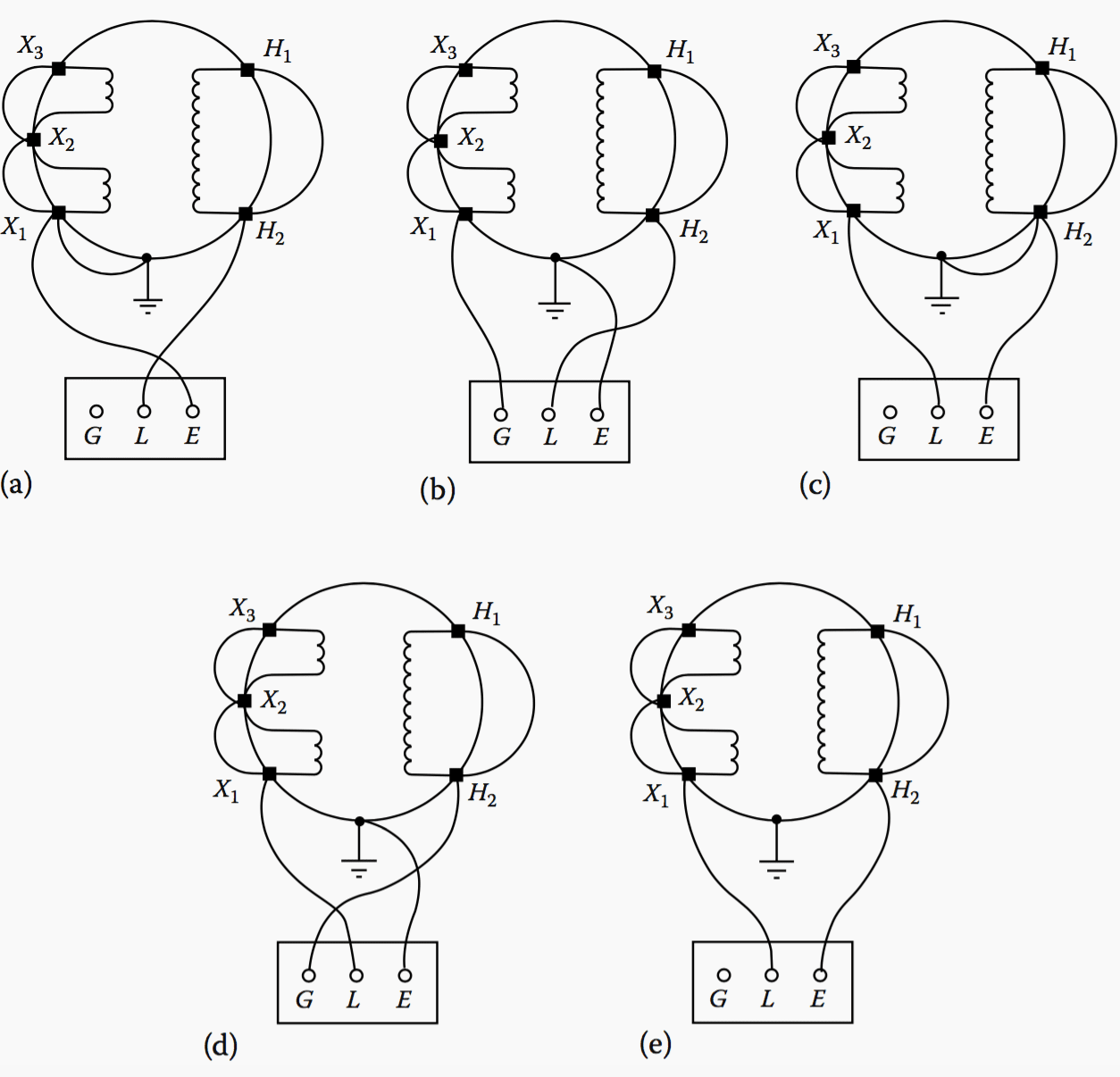
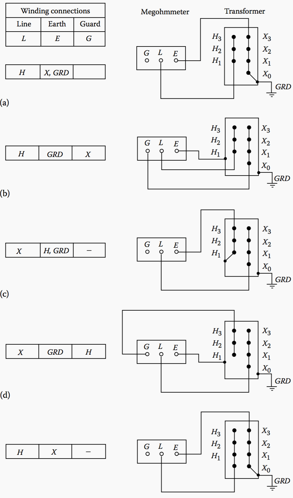
The connections for these tests are shown in Figures 1a through e and 2a through e for single-phase and three-phase transformers, respectively. Megohmmeter readings should be recorded along with the test temperature (°C).
The readings should be corrected to 20°C by the correction factors shown in Table 1.
NOTE! If the corrected field test values are one-half or more of the factory insulation readings or 1000 MΩ, whichever is less, the transformer insulation system is considered safe for a hi-pot test.
For three-winding transformers, test should be made as follows:
- High to low, tertiary and ground (H-LTG)
- Tertiary to high, low and ground (T-HLG)
- Low to high, tertiary and ground (L-HTG)
- High, low, and tertiary to ground (HLT-G)
- High and tertiary to low and ground (HT-LG)
- Low and tertiary to high and ground (LT-HG)
- High and low to tertiary and ground (HL-TG)
Also, do not make the insulation resistance test of the transformer when it is under vacuum because of the possibility of flashover to ground.
The test connections shown in Figure 2a, c, and e are most frequently used. The test connections in Figure 2b and d give more precise results. The readings obtained in the connections in Figure 2a and b are practically equal to readings in test connections in Figure 2c and d, respectively.
Where:
- Connection for high winding to low winding to ground;
- Connection for high winding to ground and low winding guarded;
- Connection for low winding to high winding to ground;
- Connection for low winding to ground and high winding guarded;
- Connection for high winding to low winding.
Acceptable insulation resistance values for dry and compound-filled transformers should be comparable to those for Class A rotating machinery, although no standard minimum values are available.
In the absence of more reliable data the following formula is suggested:
IR = CE / √ kVA
where:
- IR is the minimum 1 min 500 V DC insulation resistance in megohms from winding to ground, with other winding or windings guarded, or from winding to winding with core guarded
- C is a constant for 20°C measurements
- E is the voltage rating of winding under test kVA is the rated capacity of winding under test
| Values of C at 20°C | ||
| 60 Hz | 50 Hz | |
| Tanked oil-filled type | 1.5 | 1.0 |
| Untanked oil-filled type | 30.0 | 20.0 |
| Dry or compound-filled type | 30.0 | 20.0 |
This formula is intended for single-phase transformers. If the transformers under test is one of the three-phase type, and the three individual windings are being tested as one, then:
- E is the voltage rating of one of the single-phase windings (phase to phase for delta connected units and phase to neutral or star connected units)
- kVA is the rated capacity of the completed three-phase winding under test.
Power Transformer Testing (VIDEO)
Measuring DC winding resistance and checking the tap changer.
Reference // Electrical power equipment maintenance and testing by Paul Gill
Related electrical guides & articles


Edvard Csanyi
Hi, I'm an electrical engineer, programmer and founder of EEP - Electrical Engineering Portal. I worked twelve years at Schneider Electric in the position of technical support for low- and medium-voltage projects and the design of busbar trunking systems.I'm highly specialized in the design of LV/MV switchgear and low-voltage, high-power busbar trunking (<6300A) in substations, commercial buildings and industry facilities. I'm also a professional in AutoCAD programming.
Profile: Edvard Csanyi

It’s really amazing information regarding insulation tester, I found it good as a test engineer.thanks to EEP.
This is a fruitful and great site, we ask to send us the method of testing the MV / MV transformer insulation winding and reference C, and why a bridge is made on the phases (secondary or primary) when measuring.
Have been using the 1982 “Electrical Equipment Testing & Maintenance” book by A.S. Gill that this article is taken from for years. Lots of great information on a large variety of topics.
I am confused 315kva delta-star transformer
When i megger lv winding to body ground is
Rade zero what is it’s problem
I think you mean 315kva transformer insulation resistance(megger) of Low voltage winding to body reads zero? It means that either there could be a direct connection or touch of Low voltage winding or terminal to a body or tank of transformer or there could be a direct touch between core of transformer with LV winding.
Thank you for this article. But when I read this book “Electrical power equipment maintenance and testing” by Paul Gill, i found that the table of C values is a little bit different than you cited in your article.
So there is C values for 60Hz and 25 Hz not for 50 Hz. Can you please tell me how to calculate then the minimum IR of a transformer with this formula !
Excelente tema, yo realizo trabajos de este tipo, en mantención de transformadores de distribución, resistencia de aislación, de devanados, rigidez dielectrica de aceites aislantes usando norma ASTM D-877, indice de acidez de aceite según ASTM D-874
I don’t think there is any reason because they are all looped together internally
Does anyone have information on how you commission a circuit breaker in an electrical substation?
your information is interesting but I will remove you because you are too intrusive / aggressive with popups.
one per day was a lot. but now? 2 o 3 or 4?
Me gusta las informaciones de EEP, gracias.
Dear sir
I am confused in meggring of delta star transformer . Is that same as star-star transformer??
All other test should be treated as well including detail and vivid calculations were necessary
Respected sir ,
I am confused in the last measurement for HV & LV . in this measurement tank should be guarded otherwise what will be difference in the measurement no. a and e
What is the purpose of Step 3? Why tie the bushings together for a DC test when they are connected internally? I have heard this procedure before but no one has been able to explain WHY to do this or what will happen if a tester does not do it.
Thanks.
this article is useful and applicable. thank you
it is a great wewb site. i always use for preparing ppts for my job.( i am a technical training manager for ROTAX LTD SRILANKA..MY JOB IS TO TEACH ELECTRICAL ENGINEERING PRODUCT TRAINING FOR MARKETING AND ENGINEERING STAFF HERE. NOT A EASY JOB.