
Estimated Study Time: 7 minutes
Few words about digital multimeter
Digital multimeter has generally replaced the analog-type multimeter as the test device of choice for maintainers because they are easier to read, are often more compact and have greater accuracy. Digital multimeter performs all standard analog-meter measurement functions of AC and DC. Some offer frequency and temperature measurement.
 Basic measuring of resistance, voltage and current using digital multimeter
Many have such features as peak-hold display that provides short-term memory for capturing the peak value of transient signals as well as audible and visual indications for continuity testing and level detection.
When troubleshooting with the digital multimeter, the maintainer is able to “see” the situation and the problem within the circuit or system. Figure 1 illustrates a typical autoranging digital multimeter.
Of course for the meter to be of any use it must first be connected to the circuit or device to be tested. Both leads, one red and the other black, must be inserted into the correct meter lead jacks. The black lead is connected to the meter jack marked COM or common.
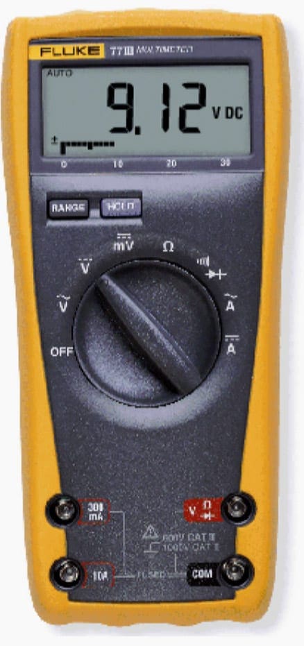
It is usually the lower right jack as in this illustration. (Be aware that not every meter has the same jack configuration.) The red lead is connected to either of the appropriate jacks depending on what the maintainer wants to measure – ohms, volts or amperes.
The two jacks on the left are utilized when measuring current, either in the 300mA or the 10 ampere range.
Let’s see now the basic procedures for measuring of three main electrical units:
1. Measuring resistance
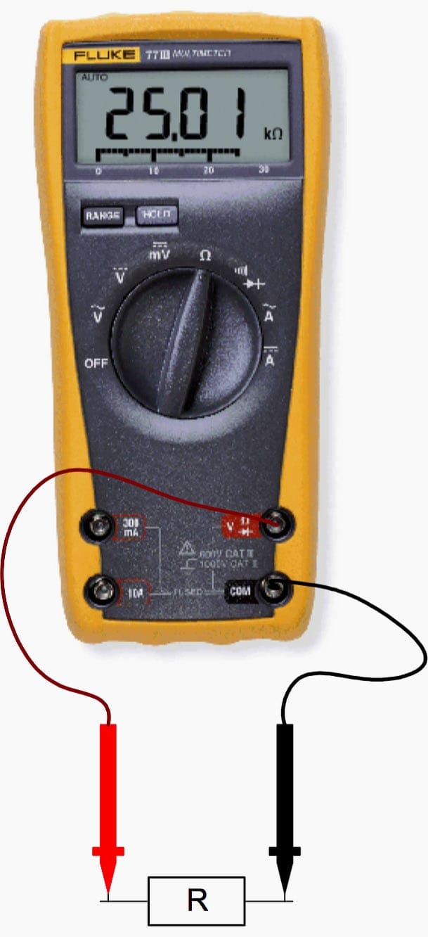
Figure 2 shows the steps that should be followed when measuring resistance. Remember that resistance measurements are carried out without the power being applied to the component under test, and resistance values can vary by as much as 20% due to the tolerance of certain resistors.
If a resistor does open, the digital multimeter display will flash on and off or display OL (open line) because the resistor has an infinite resistance.
- Turn off power to the circuit
- Select resistance Ω
- Plug the black test lead into the COM jack and the red test lead into the Ω jack
- Connect the probe tips across the component or portion of the circuit for which you want to determine the resistance
- View the reading and be sure to note the unit of measure, Ω, ΩK, MΩ, etc.
Go back to digital multimeter measurements ↑
2. Measuring voltage
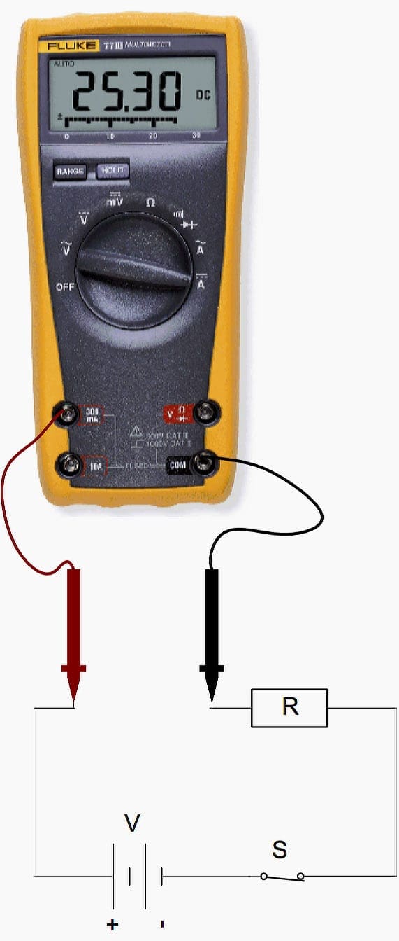
Figure 3 shows the steps that should be followed when measuring voltage. The measurement of both voltage and resistance is where the digital multimeter finds its greatest utilization.
For voltage and resistance measurement, the red lead is inserted into the V – Ω (volt or ohm) meter jack.
- Select volts AC (V~), volts DC (V—), mvolts (V—) as desired
- Plug the black test lead into the COM jack and the red test lead into the V jack
- Touch the probe tips to the circuit across a load or power source as shown (parallel to the circuit to be tested)
- View the reading being sure to note the unit of measure
Note // For DC readings of the correct polarity (+ or -), touch the red test probe to the positive side of the circuit, and the black test probe to the negative side of the circuit ground. If you reverse the connections, a digital multimeter with auto-polarity will merely display a minus sign indicating negative polarity. With an analog meter you risk damaging the meter.

Go back to digital multimeter measurements ↑
3. Measuring current
Figure 4 shows the steps that should be followed when measuring current. The measurement of current is rarely performed when troubleshooting, as the circuit path has to be opened to insert the digital multimeter in series with the current flow.
However, if current is to be measured, the red lead is inserted into one of the ampere jacks, 10 amp (10A) or 300 milliamp (300 mA) input jack depending on the expected value of the reading.
- Turn off the power to the circuit
- Disconnect, cut or unsolder the circuit, creating a place where the meter probes can be inserted
- Select amps AC (A~), or amps DC (A—) as desired
- Plug the black test lead into the COM jack and the red test lead into 10 amp (10A) or 300 milliamp (300mA) jack depending on the expected value of the reading
- Connect the probe tips to the circuit across the bread as shown so that all current will flow through the meter ( a series connection)
- Turn the circuit power back on
- View the reading being sure to note the unit of measure
Note // If test leads are reversed a negative (-) sign will be displayed
Go back to digital multimeter measurements ↑
Reference // Electrical Theory – Technology, PLC concepts, basic electronics by Michelin
Related electrical guides & articles


Edvard Csanyi
Hi, I'm an electrical engineer, programmer and founder of EEP - Electrical Engineering Portal. I worked twelve years at Schneider Electric in the position of technical support for low- and medium-voltage projects and the design of busbar trunking systems.I'm highly specialized in the design of LV/MV switchgear and low-voltage, high-power busbar trunking (<6300A) in substations, commercial buildings and industry facilities. I'm also a professional in AutoCAD programming.
Profile: Edvard Csanyi

Thought this level of information would be directed to primary school children or maybe farmers
I want to know why Star Delta Transformer is used for long high voltage transmission in electrical power system
Thanks for advance
An exercise for the readers: What is wrong with the lead photo with the automotive battery. Why does it appear to show the correct (although negative) voltage.
Paul – re. your comment:
It’s a strain on the eyesight but just possible to make out that the left-hand socket is marked something ‘A’ (a CURRENT, not voltage range). With slight magnification, I notice the second socket from the right is marked COM – which he should be using for the black lead, but isn’t.
Almost all DMMs would normally show range & status details in the display (mV or V; AC or DC; state of the meter’s internal battery). This one isn’t doing. Whether the user has noticed this, we don’t know. Maybe he’s just having a bad day! But I’m sure he realized something was wrong and immediately moved the black lead to its correct socket (COM) – thereby shorting out the battery. Still, at least he’ll now have a replacement instrument won’t he.
All in all, an excellent example of how use a digital multimeter!