
Estimated Study Time: 25 minutes
Medium Voltage Circuit Breakers
When you look at the IEC 62271-100 for MV breaker ratings, you will likely find a bunch of rated-something ratings. It could be hard for young engineers to catch up with all ratings, especially since several ratings are similar in wording but crucially different. This technical article will shed some light on the most important of these ratings of a medium-voltage circuit breaker.
 Mastering Operational Ratings of Medium-Voltage Switchgear
The last two decades have seen tremendous advancements in the technology of medium voltage circuit breakers. Nowadays, the majority of utility systems use a combination of SF6 circuit breakers and vacuum. When it comes to transmission voltages (72.5 kV and higher), the SF6 circuit breaker is now considered cutting edge technology. But because it is a greenhouse gas, many nations have introduced safety measures to keep SF6 gas from getting into the air.
The ratings of circuit breakers, including SF6 and vacuum breakers, are briefly covered in this technical article.
- Operation of a MV circuit breaker
- Circuit breaker construction:
- Mechanical operation:
- Withdrawable circuit breakers
- Control methods
- IEC Ratings:
- Rated voltage, Ur (kV)
- Rated lightning impulse withstand rating, Up (kV)
- Rated frequency, fr (Hz)
- Rated current, Ir (A)
- Rated short-time withstand current, Ik (kA)
- Rated short circuit duration, tk (s)
- Rated peak withstand current (kA)
- Rated short circuit breaking capacity, Isc (kA)
- Transient recovery voltage, TRV
- Rated TRV (Uc) for circuit breakers intended for use on cable systems
- Rated out-of-phase breaking current, Id (kA)
- Rated capacitive switching currents
- IEC Classifications
- Attachment (PDF) 🔗 Download ‘Substation Cable Installation Guide’
1. Operation of a MV circuit breaker
A circuit breaker is a main switching device, providing control and protection of an electrical circuit. It is a very fast acting device, capable of switching high fault current levels. Some medium voltage circuit breakers have integrated current monitoring and protection facilities, but in most cases external current transformers and a protection relay are required to trip the circuit breaker under abnormal conditions.
A circuit breaker must operate under various conditions without damage or safety risk to personnel:
Condition #1: A circuit breaker operates mostly in the closed position and must continuously sustain its rated current without exceeding its thermal limits.
Condition #2: In the closed position, a circuit breaker must sustain a specific fault current level (Ik) for a short time period (tk). A circuit breaker’s short-time withstand fault current rating must exceed the expected rms symmetrical fault current level (Is) at the point of installation.
Condition #3: A circuit breaker must be capable of sustaining electrodynamic and thermal stresses associated with the peak let-through energy of a fault. The circuit breaker’s make rating must exceed the expected peak fault current level (Ip) at the point of installation.
- Ip = 2.5 × Is (for a 50 Hz supply with a 45 ms DC time constant)
- Ip = 2.6 × Is (for a 60 Hz supply with a 45 ms DC time constant)
Where:
- Ip = asymmetrical peak let-through fault current, from the first fault loop (kA)
- Is = rms symmetrical fault current level, with no DC component (kA)
Figure 1 – MV circuit breaker current-time diagram
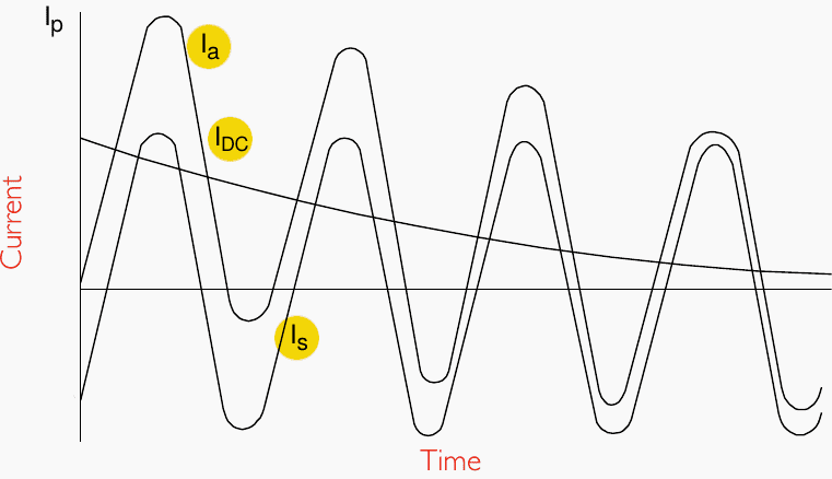
Where:
- Ia – asymmetrical rms current
- IDC – DC component
- Is – symmetrical rms component
- Ip – instantaneous peak current
2. Circuit breaker construction
Main switching contact design has two primary components:
- a suitable insulation medium to minimise the physical size of the apparatus
- a method to reduce any arc and extinguish it during contact breaking
2.1 Vacuum circuit breakers
Typical characteristics:
- Environment: Indoor
- Operating current: ≤ 3000 A
- Operating voltage: ≤ 36 kV
- Fault current rating: ≤ 31.5 kA
- Contacts: One fixed and one moveable copper/chromium switching contact per pole, with a contact separation distance of 10-15 mm. Contacts reside in a vacuum, within a totally sealed cast resin enclosure.
- Arc-extinguishing properties: good
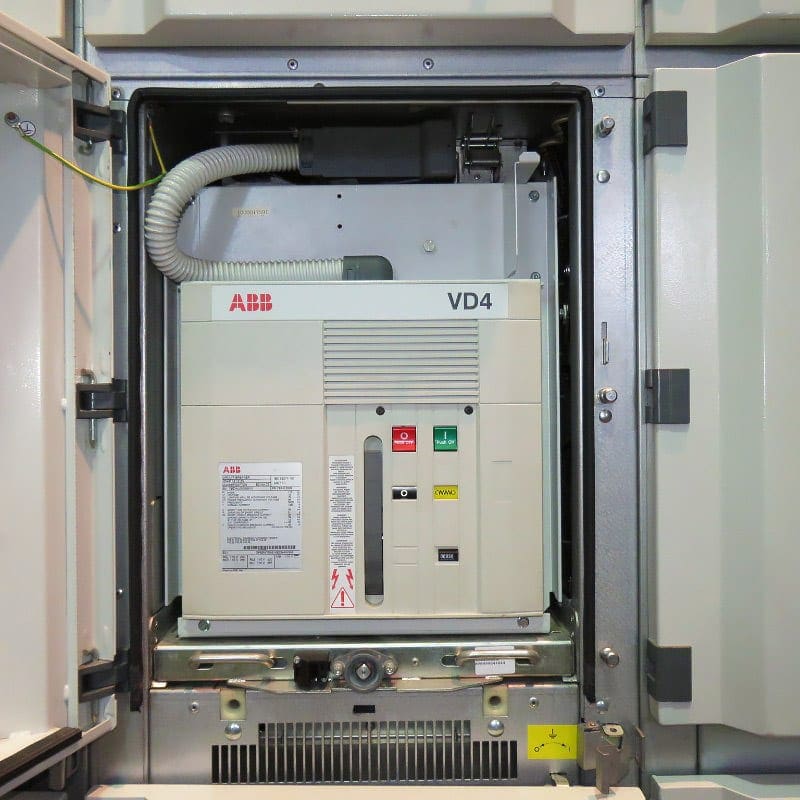
Figure 2 – Medium voltage draw-out vacuum circuit breaker, type VD4 (ABB)
2.2 SF6 gas-insulated circuit breakers
Typical characteristics:
- Environment: Indoor/outdoor
- Operating current: ≤ 4000 A
- Operating voltage: ≤ 52 kV
- Fault current rating: ≤ 50 kA
- Contacts: One fixed and one moveable copper/chromium switching contact per pole, with a contact separation distance of 10-15 mm.
- Arc-extinguishing properties: quick and efficient (Special design techniques use compressed sulphur hexafluoride gas to extinguish the arc)
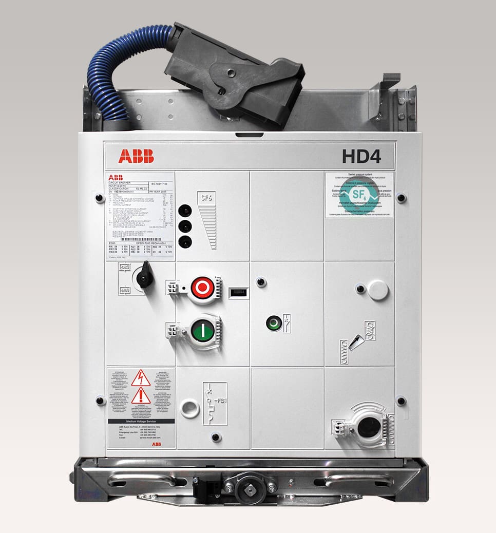
Figure 3 – Medium-voltage SF6 circuit breaker, type HD4 (ABB)
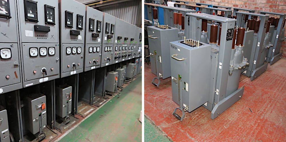
2.3 Oil circuit breakers (Obsolete)
These circuit breakers use an oil blast method to extinguish the arc. When the switching contacts separate, the arc vaporises the oil surrounding it. This produces a gas which inhibits arc ionisation. At the same time, convectional movement of the oil aids in cooling after the arc has been extinguished.
Due to oil fire hazard, these circuit breakers are generally used for outdoor applications only, and are being replaced in indoor applications.
Figure 4 – Old medium-voltage oil circuit switchgear (left) and oil circuit breakers (right)
3. Mechanical operation
The most critical characteristics of a circuit breaker are the opening and closing velocity values, along with the stroke or travel distance. They are generally dictated by the requirements imposed by contacts. The opening and closing velocities are crucial for the contacts to prevent contact erosion and contact welding.
The circuit breaker stroke is fundamentally associated with the circuit breaker’s capacity to withstand the required operating dielectric thermal stresses, which has a direct relationship to the total contact gap and the rate of its expansion.
Circuit breakers are electromechanically driven using magnetic or stored energy techniques.
3.1 Magnetic technique
Magnetic technique uses an open and close armature, permanently energized in one of the two states. The energy required to maintain constant magnetic field strength, in either the open or closed state, is stored using capacitance. Energised armatures interact with mechanical linkages to operate the main switching contacts.
This operating technique provides extremely fast operation and is very energy efficient.
All components are mounted on a single axis, with a mono-stable magnetic actuator (one per pole). The actuators power a pulling insulator, which links to the vacuum interrupters at the top of the breaker.
Figure 5 – MV circuit breaker with magnetic operating mechanism (Tavrida)
3.2 Stored energy technique
Stored energy technique incorporates an opening and closing spring. Each spring is charged with potential energy, by motor operation, or by using a manually operated handle in case of auxiliary power loss. Mechanical operation of the main switching contacts occurs by releasing the potential energy from a charged spring.
Spring release is activated electrically by the use of small opening and closing solenoids or by manual pushbuttons which operate mechanical latches.
Figure 6 – Close and charging motor control operating mechanism of Siemens’s medium-voltage vacuum circuit breaker[/highlight2]

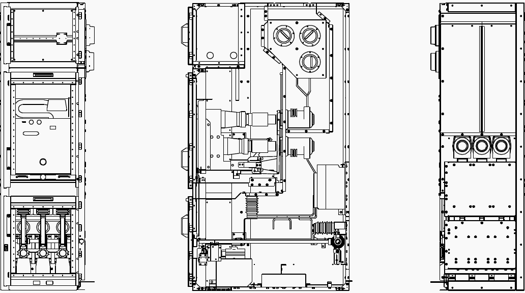
4. Withdrawable circuit breakers
Most indoor switchgear installations use withdrawable circuit breakers. These are also referred to as rack style or draw-out units. The main circuit breaker body is fitted on a trolley arrangement known as a truck, which is moved horizontally by means of a crank handle. By moving the circuit breaker towards the operator, the main contact points separate until a test position is reached.
To reconnect the main contact points, the circuit breaker is moved away from the operator until the service position is reached. The circuit breaker position cannot be changed unless the circuit breaker main poles are electrically open.
When a withdrawable circuit breaker is integrated into a metal-enclosed switchgear compartment, electromechanical interlocking is used to ensure safe operation, such as:
- The circuit breaker switchgear compartment door cannot be opened unless the circuit breaker is electrically open and physically racked out to the test position.
- Isolation barrier shutters are automatically operated, according to the circuit breaker truck position.
- when an earth switch is incorporated into a metal-enclosed switchgear panel with a withdrawable circuitbreaker, the earth switch can only be closed if the circuit breaker is electrically open and physically racked-out to the test position’
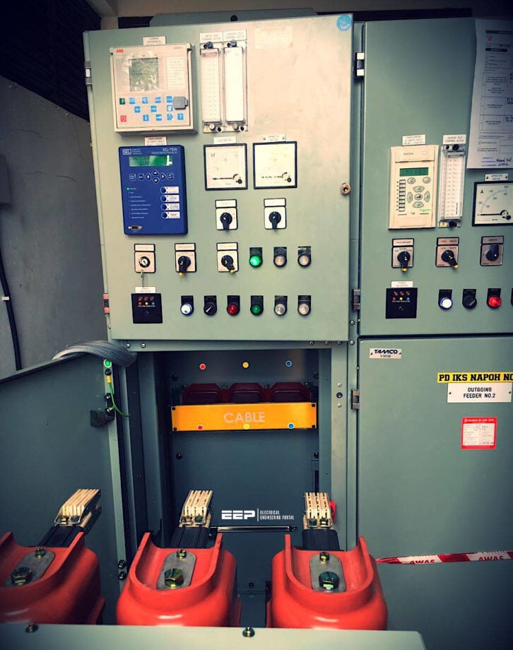
Figure 7 – MV switchgear cubicle with a withdrawable circuit breaker
Watch Video – Circuit breaker construction explained in a detail
5. Control methods
Table 1 – Compatibility between circuit breaker types and control methods
| Circuit breaker type | Electrical control method | Manual control | |
| Single command operated (SCO) control signal | Double command operated (DCO) control signal | Pushbuttons mounted on circuit breaker | |
| Withdrawable, magnetically operated | ✔ | ✔ | ✔ |
| Withdrawable, stored energy operated | ✔ | ✔ | ✔ |
| Fixed, magnetically operated | ✔ | ✔ | ❌ |
| Fixed, stored energy operated | ✔ | ✔ | ❌ |
Where:
- SCO control uses a single contact.to close the circuit breaker. This contact is maintained open to trip the circuit breaker and maintained closed
- DCO control uses two momentary, normally open contacts. One contact is pulsed closed to trip the circuit breaker. The other contact is pulsed closed to close the circuit breaker.
6. IEC Ratings
Medium voltage circuit breakers must be type tested to provide standard ratings. The most commonly used standards for this testing are IEC 62271-1 and IEC 62271-100. The following information provides details of some of the more common ratings which must be marked on the circuit breaker nameplate after type testing.
6.1 Rated voltage, Ur (kV)
Maximum operating voltage (rms) the device can continuously withstand during normal operation. The rated voltage must be greater than or equal to the system’s operating voltage.
Standard values for Ur: 3.6, 7.2, 12, 17.5, 24, 36 kV (source: IEC 62271-1)
6.2 Rated lightning impulse withstand rating, Up (kV)
This is the peak voltage the device can withstand for a 1.2/50 µs standard test wave.
Table 2 – Standard values for Up (source: IEC 62271-1)
| Ur (kV) | 3.6 | 7.2 | 12 | 17.5 | 24 | 36 |
| Up (kV) | 40 | 60 | 75 | 95 | 125 | 170 |
6.3 Rated frequency, fr (Hz)
This rating must match the system’s operating frequency. Rated frequency only has to be marked on the device nameplate if it is not suitable for 50 Hz and 60 Hz operation.
6.4 Rated current, Ir (A)
This is the rms level of current which can continuously flow through a device without exceeding its maximum allowable contact temperature rise. Temperature rise limits are defined in IEC 62271-1, for an ambient temperature of 40 °C. The rated current must be greater than the maximum expected load current, at the point of installation.
Standard values for Ir: 630, 800, 1000, 1250, 1600, 2000, 2500, 3150, 4000 A (source: IEC 62271-1)
Further Study – Guide to Secondary Injection Testing of the Current Transformers
Comprehensive Guide to Secondary Injection Testing of the Current Transformers (Part 1)
6.5 Rated short-time withstand current, Ik (kA)
This is the maximum rms symmetrical fault current the device can withstand, for a short time period, without risk of damage. This rating must be higher than the prospective rms fault current at the point of installation.
Ik ≥ Is
Is = Ssc / √3 × U
Where:
- Ik = Short-time withstand current rating (kA)
- Is = Prospective rms fault current (kA)
- Ssc = System short circuit power (kVA)
- U = System operating voltage (kV)
Standard values for Ik: 6.3, 8, 10, 12.5, 16, 20, 25, 31.5, 40, 50, 63 kA (source: IEC 62271-1)
6.6 Rated short circuit duration, tk (s)
This is the time the device can endure its rated short-time withstand current (Ik) without damage. This value must be greater than the total expected clearing time of a fault at the point of installation.
Standard values for tk: 0.5, 1, 2, 3 seconds (source: IEC 62271-1)
IMPORTANT NOTE: If the value of tk is not 1 second, the rated short circuit duration must be published on the circuit breaker nameplate.
6.7 Rated peak withstand current (kA)
This is the maximum peak fault current level which the device is able to close (make) on. This rating must be greater than the expected peak let-through fault current (Ip) at the point of installation.
Rated peak withstand current ≥ Ip
- Ip = 2.5 × Is (for a 50 Hz supply with a 45 ms DC time constant)
- Ip = 2.6 × Is (for a 60 Hz supply with a 45 ms DC time constant)
Where:
- Ip = Asymmetrical peak let-through fault current, from the first fault loop (kA)
- Is = RMS symmetrical fault current level, with no DC component (kA)
Source: IEC 62271-1, IEC 62771-100
Related Study – IEC/NEMA/IEEE ratings of current transformers (CTs) in MV applications
IEC and NEMA/IEEE ratings of current transformers (CTs) in medium voltage applications
6.8 Rated short circuit breaking capacity, Isc (kA)
This is the highest level of rms current which the circuit breaker can successfully open (break) on a fault, at its rated voltage. When a short circuit occurs in a 3-phase system, the initial fault current is asymmetrical and is made up of an AC symmetrical component and a decaying DC component.
The rated short circuit breaking capacity must be greater than the expected asymmetrical fault current level when the circuit breaker poles are opened.
- ISC ≥ Ia
- Ia = Is + Id
Where:
- Isc = Rated short circuit breaking capacity of circuit breaker (kA)
- Ia = Asymmetrical fault current level when circuit breaker poles are opened (kA)
- Is = AC symmetrical fault current component (kA)
- Id = DC fault current component (kA)
Standard values for Isc = 6.3, 8, 10, 12.5, 16, 20, 25, 31.5, 40, 50, 63 kA (source: IEC 62271-100)
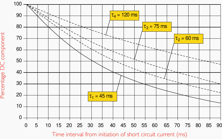
The graph below illustrates the percentage DC component of a fault, over a period of time, for systems with various time constants. Most systems use the standard time constant (τ1) of 45 ms. The total opening time of the circuit breaker is the pole opening time plus 10 ms for relay sensing, and this figure can be used to determine the percentage DC component of a fault at the instant of breaking.
Figure 8 – Percentage DC component in fault current
6.9 Transient recovery voltage, TRV
TRV is the voltage transient that appears across a circuit breaker pole when current flow is interrupted at its rated voltage. TRV waveforms vary, depending on the characteristics of the supply and the load. IEC 62271-100 specifies test conditions under which the circuit breaker must endure standard TRV waveforms.
The test results are published as specific circuit breaker nameplate ratings.
For 3-phase circuits, TRV refers to the voltage that will appear across the first pole to open. The ratio of TRV to single phase voltage is referred to as the first-pole-to-clear factor and is 1.5 for systems up to 72.5 kV.
Figure 9 – Transient Recovery Voltage
6.10 Rated TRV (Uc) for circuit breakers intended for use on cable systems (Class S1)
IEC 62271-100 defines standard TRV peak voltage ratings.
Table 3 – TRV withstand ratings for short circuit breaking current Isc
| Ur (kV) | 3.6 | 7.2 | 12 | 17.5 | 24 | 36 |
| Uc (kV) | 6.2 | 12.3 | 20.6 | 30 | 41.2 | 61.7 |
Source: IEC 62271-100
Uc = 1.715 × Ur
Where:
- Uc = TRV peak voltage value (kV)
- Ur = rated voltage (kV)
Figure 10 – Voltage envelope for a two parameter TRV waveform on a cable system less than 100 kV
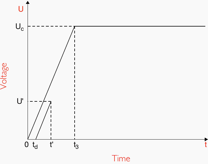
Source: IEC 62271-100
6.11 Rated out-of-phase breaking current, Id (kA)
When a circuit breaker opens with its input and output voltages out-of-phase, larger than normal voltages will appear across the circuit breaker poles. This condition reduces the circuit breaker’s maximum breaking current capability.
Table 4 – TRV withstand ratings for out-of-phase current Id
| Ur (kV) | 3.6 | 7.2 | 12 | 17.5 | 24 | 36 |
| Uc (kV) | 9.2 | 18.4 | 30.6 | 44.7 | 61.2 | 91.9 |
Source: IEC 62271-100
Uc = 2.551 × Ur
Where:
- Uc = TRV peak voltage value (kV)
- Ur = rated voltage (kV)
Related Course – MV Switchgear Schematics Course: Tripping, Trip Circuit Supervision, Interlocking and Indication Circuits
6.12 Rated capacitive switching currents
IEC 62271-100 recommends capacitive switching current ratings for circuit breakers, based on the following conditions:
- Ic = rated cable charge breaking current (A)
- Isb = rated single capacitor bank breaking current (A)
- Ibb = rated back-to-back capacitor bank breaking current (A)
- Ibi = rated back-to-back capacitor bank inrush making current (kA)
IMPORTANT NOTE! These ratings are recommendations only. Individual circuit breaker ratings may specify different values.
Table 5 – Preferred values of rated capacitive switching currents (Derived from IEC 62771-100)
| Rated voltage | Rated cable charging breaking current | Rated single capacitor bank breaking current | Rated back-to-back capacitor bank breaking current | Rated back-to-back capacitor bank inrush making current |
| Ur (kV rms) | Ic (A rms) | Isb (A rms) | Ibb (A rms) | Ibi (kA) |
| 3.6 | 10 | 400 | 400 | 20 |
| 7.2 | 10 | 400 | 400 | 20 |
| 12 | 25 | 400 | 400 | 20 |
| 17.5 | 34.5 | 400 | 400 | 20 |
| 24 | 31.5 | 400 | 400 | 20 |
| 36 | 50 | 400 | 400 | 20 |
Further Study – MV/HV switchgear (circuit breaker) switching capability and suitability for specific applications
MV/HV switchgear (circuit breaker) switching capability and suitability for specific applications
7. IEC Classifications
Medium voltage circuit breakers can be type tested and categorised according to the classifications in IEC 62271-100.
Table 6 – Classifications of switching devices (Source: IEC 62271-100)
| Class | Description |
| C1 | Low probability of restrike during capacitive switching |
| C2 | Very low probability of restrike during capacitive switching |
| E1 | Standard electrical endurance |
| E2 | Extended electrical endurance, designed so no maintenance of circuit interrupting parts is required during the expected operating life |
| M1 | Standard mechanical endurance (2000 operations) |
| M2 | Extended mechanical endurance (10000 operations) |
| S1 | Intended for use on cable systems |
| S2 | Intended for use on overhead line systems |
8. Attachment (PDF): Substation Cable Installation Guide
Download: Substation Cable Installation Guide (for premium members only):
Related electrical guides & articles


Edvard Csanyi
Hi, I'm an electrical engineer, programmer and founder of EEP - Electrical Engineering Portal. I worked twelve years at Schneider Electric in the position of technical support for low- and medium-voltage projects and the design of busbar trunking systems.I'm highly specialized in the design of LV/MV switchgear and low-voltage, high-power busbar trunking (<6300A) in substations, commercial buildings and industry facilities. I'm also a professional in AutoCAD programming.
Profile: Edvard Csanyi

Unable to download and save.