
Estimated Study Time: 19 minutes
Similar to LV motors, but different
In principle, the protection of medium voltage motors is similar to low voltage motors, but the requirements are more demanding. Being closer to the utility source, medium-voltage motors are more susceptible to voltage sags and surges, reclosing, and higher available fault levels.
 The basics of fault protection for medium voltage motors (photo credit: Soltecpro SAC)
Because of the higher bus voltage and load currents, instrument transformers are used to reduce these currents to lower values, which are used with protective relays. The most common instrument transformer secondary ratings are 120 V for voltage transformers (VTs) and 5 A for CTs.
The circuit breakers (i.e., air, sulfur hexafluoride (SF6), vacuum), instrument transformers, and protective relays are mounted in switchgear.
- Motor overcurrent differential relay (Device 87)
- Split winding current unbalance (Device 87)
- Ground-fault protection
MV Motor Fault protection
1. Motor overcurrent differential relay (Device 87)
Motor overcurrent differential protection measures the current flow into a load and compares it to the current measured on the neutral side of the motor. A current difference is detected as a fault. These schemes can be technically applied to any motor load, but often are applied to large or critical motors only where damage could be costly or replacement difficult.
Three general recommendations for applying differential overcurrent protection are as follows:
- With all motors 750 kW and above used on ungrounded systems.
- With all motors 750 kW and above used on grounded systems where the ground-fault protection applied is not considered sufficient without differential protection to protect against phase-to-phase faults.
- With smaller motors, especially at voltages above 2400 V, although justifying differential protection for large motors (i.e., 1900 kW and above) is easier.
1.1 Phase differential overcurrent relay
Phase differential overcurrent relay is used to sense low-level phase faults and to quickly remove the motor circuit before extensive damage develops.
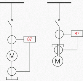
This scheme uses six identical CTs (i.e., one pair for each phase) and three relays (i.e., one per phase). The CTs should be sized to carry full-load current continuously and to not saturate during an external or internal fault (see Figure 2). The currents from each pair of CTs circulate through the relay-restraining windings under normal (i.e., no-fault) conditions.
While sometimes applied to delta-connected motors, this scheme is usually used with wye-connected motors. Note that wye-connected motors are much more common than delta-connected ones in the larger horsepower ratings.
With the wye-connected motor, three of the CTs are normally located at the starter (or motor switchgear) and the other three in the three phases at the motor winding neutral.

1.2 Self-balancing differential using window CTs
Three window (or toroidal) CTs are normally installed at the motor. One CT per phase is used with the motor line, and neutral leads of one phase are passed through it so that the flux from the two currents normally cancels each other in the CT. A winding phase-to-phase or phase-to-ground fault results in an output from the CTs of the associated phases. That current operates the associated relays (see Figure 3).
The CTs and relays would normally be the same as the CTs and relays used for zero-sequence instantaneous ground overcurrent protection (see 3.1 Instantaneous ground-fault protection) with the relay set between 0.25 A and 1.0 A pickup.
Therefore, this differential scheme usually has a lower primary pickup in amperes than the conventional differential scheme because the CT ratio is usually greater with the conventional scheme.

This differential scheme has a slight advantage over the scheme in Figure 2 in detecting ground faults. For motors installed on grounded systems this difference is significant because most faults begin as ground faults.
The usual objective of motor-fault protection is to remove the fault before the stator iron is significantly damaged.
With the CTs located at the motor, this scheme does not detect a fault in the cables supplying power to the motor. A fault in these cables would normally be detected by the overcurrent protection.
For large motors, coordinating the supply phase-overcurrent protection with the motor overcurrent protection is often a problem. The presence of motor differential protection is sometimes considered to make this coordination less essential. In this regard, the conventional differential is better than the self-balancing differential because the motor cables are also included in the differential protection zone.
Hence coordination between the motor differential and supply phase-overcurrent relays is complete.
As with zero-sequence ground-fault overcurrent protection, testing the overall CT and relay combinations is important during commissioning. Current in a test conductor should be passed through the window of each CT. Because normally the relays do not carry current, an open circuit in a CT secondary or wiring to a relay can be discovered by this overall testing.
2. Split winding current unbalance (Device 87)
The purpose of the split winding current unbalance device is to quickly detect low-magnitude fault conditions. This protection also serves as backup to instantaneous phase-overcurrent and ground-fault overcurrent protection.
This protection is normally only applied to motors having two (or three) winding paths in parallel per phase (see Figure 4).
2.1 Arrangement of CTs and relays
The usual application is with a motor having two winding paths in parallel per phase. The six line leads (i.e., two per phase) of the motor are brought out, and one CT is connected in each of the six leads. The primary current rating of the CTs should be chosen to carry full-load current.
The currents from each pair of CTs, associated with the same phase, are subtracted, and their difference is fed to a short-time inverse time-overcurrent relay. Three of these relays are required (i.e., one per phase), and each is set at 1.0 time dial and between 0.5 A and 2.5 A.
The relay should be set above the maximum current unbalance that can occur between the two parallel windings for any motor-loading condition.
2.2 Evaluation of split winding current unbalance protection
The following factors should be considered when evaluating split winding current unbalance protection:
- Total cost would be somewhat less than conventional phase differential and more than self-balancing differential.
- The primary pickup current for this protection would be about half of the primary pickup current of conventional phase differential because both schemes require the CT primaries to be rated to carry normal load currents. Self-balancing differential would usually have a lower primary pickup in amperes.
- This protection has a slight time delay compared to the phase differential schemes.
- When the CTs are located in the motor starter, split winding protection has the same advantage over self-balancing differential as does conventional phase differential, namely, it detects a fault in the motor cables and may facilitate coordination with the supply feeder overcurrent relays (see 1.2 Self-balancing differential using window CTs).
- The salient feature that this protection provides, and no other motor protection has, is the ability to sense short-circuited winding turns.The number of turns that must be short-circuited before detection occurs depends upon the motor winding arrangement, the relay pickup, and CT ratio. An analysis of the specific motor winding would be required to determine the worthiness of this feature. Short-circuited turns could cause a ground fault, which could be detected by the self-balancing differential scheme before this split winding protection would sense the short-circuited turns condition.
- This protection could be applied to a motor with four winding paths in parallel per phase by grouping them as two pairs as if only two paths in parallel existed (i.e., six CTs and three relays are used).
g) A split differential scheme is often effectively used where one CT is in one of the parallel paths and the other CT sees the total phase current.
2.3 Application of split winding protection
Split winding protection is rarely used, but is feasible to apply to important motors rated above 3700 kW that have two or four winding paths in parallel per phase.
3. Ground-fault protection
The purpose of ground-fault protection is to protect motors by detecting ground-fault conditions with no intentional delay and to be certain that the unbalance current represents a true ground fault (i.e., not due to asymmetry in the primary current or to CT saturation).
Following this detection, the protection may trip the motor circuit or only alarm, depending upon the voltage and facility operating practice.
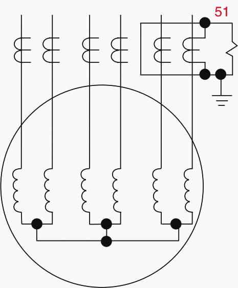
3.1 Instantaneous ground-fault protection
Using a zero-sequence (or window) CT that has been designed for instantaneous ground-fault protection and tested with a specific ground-fault relay is recommended (see Figure 5).
For medium-voltage applications, the power system should be resistance-grounded, and the Device 50G should be set to operate for a primary ground-fault current in the range of 10 A to 30 A. A suitable time delay should be added when the installation has surge protection on the motors.

3.2 Time-overcurrent ground-fault protection
Many installations have surge protection at the motor terminals, and a surge discharge through an arrester could cause an instantaneous relay to have a false trip. To avoid this event, a Device 51G should be applied, in place of the Device 50G in Figure 5 above, and set to trip within a few seconds of the fault-sensing pickup.
3.3 Installation of cable for ground-fault protection
The following precautions should be observed in applying the relay and zero-sequence CT and in installing the cables through the CT:
Precaution #1 – If the cable passes through the CT window and terminates in a pothead on the source side of the CT, the pothead should be mounted on a bracket insulated from ground. Then the pothead should be grounded by passing a ground conductor through the CT window and connecting it to the pothead.
Precaution #2 – If metal-covered cable passes through the CT window, the metal covering should be kept on the source side of the CT, insulated from ground.
The terminator for the metal covering may be grounded by passing a ground conductor through the CT window and then connecting it to the terminator.
Precaution #3 – Cable shields should be grounded by passing a ground conductor through the CT window and then connecting it to the shields per Figure 6.

Precaution #4 – The overall CT and ground relay scheme should be tested by passing current in a test conductor through the CT window.
Because normally no current exists in the relay, an open circuit in the CT secondary or wiring to the relay can be discovered by this overall test.
3.4 Residually connected CTs and ground-fault relay
Applications have been made using the residual connection from three CTs (i.e., one per phase) to supply the relay. This arrangement is not ideal because high phase currents (e.g., due to motor starting inrush or phase faults) may cause unequal saturation of the CTs and produce a false residual current.
A Device 51N installed in the residual connection would be more appropriate for these installations.
3.5 Selection of resistor for low-resistance system grounding
The purpose of resistance grounding is to provide current sufficient for protective relays to operate upon detection of a ground fault, but low enough to limit the magnitude and resulting damage to the motor.
Selection of the ground resistor should also consider the number of steps in ground-fault overcurrent protection coordination. On this basis, the ground resistor chosen for the system neutral grounding normally limits the ground-fault current within the range of 400 A to 2000 A.
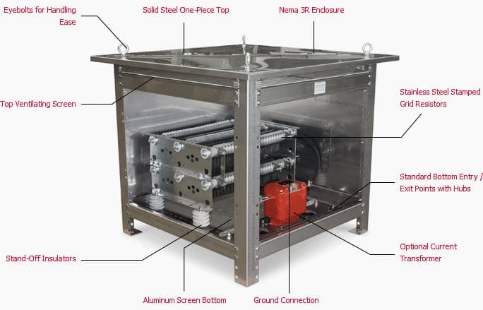
However, some companies prefer neutral ground-fault current limited to 200 A to 800. A This difference emphasizes the need to coordinate the protection of a system. A 10 s time rating is usually chosen for the resistor.
Resistance Grounding Systems have many advantages over solidly grounded systems including arc-flash hazard reduction, limiting mechanical and thermal damage associated with faults, and controlling transient overvoltages. High resistance grounding systems may also be employed to maintain service continuity and assist with locating the source of a fault.
When designing a system with resistors, the design/consulting engineer must consider the specific requirements for conductor insulation ratings, surge arrestor ratings, breaker single-pole duty ratings, and method of serving phase-to-neutral loads.
Sources:
- IEEE Recommended Practice for Protection and Coordination of Industrial and Commercial Power Systems
- Resistance Grounding System Basics by Michael D. Seal, P.E., GE Senior Specification Engineer
Related electrical guides & articles


Edvard Csanyi
Hi, I'm an electrical engineer, programmer and founder of EEP - Electrical Engineering Portal. I worked twelve years at Schneider Electric in the position of technical support for low- and medium-voltage projects and the design of busbar trunking systems.I'm highly specialized in the design of LV/MV switchgear and low-voltage, high-power busbar trunking (<6300A) in substations, commercial buildings and industry facilities. I'm also a professional in AutoCAD programming.
Profile: Edvard Csanyi

Hi,
Could you please let me know the electrical design criteria that rules:
1. Protect the person
2. Protect the device
3. Protect the process
Thanks
Sourcing Information about Electrical Tests
Hi, thanks for your useful content, i have a question, why in the MV induction motor starting we have unequal saturation in the CTs but in the inrush current of transformer starting isn’t like this?
Thanks
Great explanation. Very useful.
what is differential fault in motors?
Quality content & simple explanations
Good
This paper described MV Motor protection in nutshell, but covered entire system.
Nice! Thank you.