
Estimated Study Time: 25 minutes
What is a MV Soft Starter?
A soft starter is an electronic motor controller used on three phase medium voltage squirrel cage induction motors. During motor starting, the soft starter controls the voltage or current supplied to the motor. Motor start performance is optimized by reducing the total start current while optimizing the torque produced by the motor.
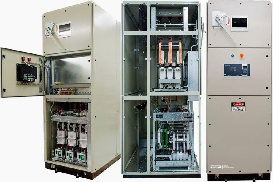 Medium voltage soft starter for heavy-duty motor control - Operation and special applications (on photo: left: Front view of MV soft starter (Aucom, type 'MVS') panel with door open, MVS power assembly is located in lower section; center: Side view of MVS panel with panels removed; right: Front view of a typical MVS soft starter)
This technical article aims to help electrical engineers in the field of medium voltage to understand how soft starter works, what benefits they offer in motor control and finally the main applications where they are used.
As an example, in schemes were used Aucom’s soft starters.
1. Soft starter technology
As stated above, the performance of motor start is optimized by reducing the total start current. Motor stopping can also be controlled by ramping down the output voltage over a predetermined time period. This is particularly useful for eliminating water hammer in pumping applications.
Controlling the voltage controls the current supplied to the motor. The stepless control of motor terminal voltage eliminates the current and torque transients associated with electromechanical forms of reduced voltage starting, such as star-delta or autotransformer starters.

A soft starter designed to control motor voltage is referred to as an open loop controller. A soft starter designed to control motor current is referred to as a closed loop controller.
1.1 Open loop soft start control
Open loop soft start controllers have no feedback of the starting performance to the controller and follow preset voltage transitions controlled by timers. Open loop soft start controllers can use a voltage step or timed voltage ramp approach.

Voltage step soft start control
Voltage step controllers (also called pedestal controllers) apply a preset level of voltage at start, then step to full voltage after a user-defined period. Voltage step starters have little advantage over closed transition electromechanical starters and are rarely used.

Where:
- Initial start voltage
- Start time
- Full voltage
Timed voltage ramp control
Timed voltage ramp controllers ramp the voltage from a user-defined start voltage to full voltage, at a controlled rate. Timed voltage ramp is used extensively in low cost soft starters.

Where:
- Initial start voltage
- Start time
- Full voltage
A high inertia load requires a slow ramp time if the current is to be minimized. If the start voltage rises to quickly, current may approach locked rotor current. A low inertia load requires a short ramp time.
Excessive starting time can result in insufficient voltage for stable operation once the motor has reached full speed.
1.2 Closed loop soft start control
Closed loop soft starters have one or more feedback loops, which monitor characteristics at the motor. The starter adjusts the voltage to the motor, in order to control the monitored parameters.

Where: 1 is Current transformer feedback.
Common closed loop systems are:
- Constant Current or Current Limit
- Timed Current Ramp
- Constant Acceleration
1.2.1 Constant current soft start
Constant current starters monitor the starting current. Increasing or decreasing the output voltage increases or decreases the current supplied to the motor. As the motor accelerates, the stator impedance rises and in order to maintain a constant current the voltage also rises. The exact relationship between voltage and speed depends on the motor design.
With a constant current starter, full torque is available as the motor reaches full speed.
1.2.2 Timed current ramp soft start
Timed current ramp soft starters increase the current from a selected start level to the maximum start current, at a controlled rate. This caters for variation in starting torque requirements, or can deliver reduced starting torque without limiting the maximum starting torque.
Typical applications are conveyors which start under varying load conditions, and pumps which require very low torque at low speed.
This method also suits motors running on generator supplies, as the starting load is gradually applied to the generator set. This provides stable voltage and frequency control of the generator set during motor starting.
1.2.3 Constant acceleration soft start
Constant acceleration or linear acceleration starters monitor the motor speed, by means of a tacho generator attached to the motor shaft. The voltage applied to the motor is controlled to deliver a constant rate of acceleration, over a selected acceleration time.
A current limiting circuit can also be used to limit the maximum starting current, particularly in applications where a potential exists for jammed loads.

Where:
- Full voltage start current
- Current limit
- Full voltage start torque
- Torque output at current limit
- Acceleration torque
- Load torque curve
2. Benefits of using soft starter
Electrical Benefits
- Minimize start current levels to match application requirements. This reduces overall demand on the electrical supply.
- Eliminate current transients during motor starting and stopping. This avoids supply voltage dips which can affect the performance of other equipment and in severe situations, cause equipment failure.
- Reduce the size of electrical transformers, switchgear and cable.
- Reduce maximum demand charges from the electricity supplier.
Mechanical Benefits
- Minimize start torque levels to match application requirements. This eliminates mechanically damaging torque transients associated with electromechanical starting methods.
- Smooth, stepless torque is applied to the load from the motor shaft. This can:
- Reduce pipeline pressure surges and water hammer in pump applications
- Eliminate belt slippage associated with belt driven loads
- Eliminate belt slap associated with large belt conveyor applications.
- Reduce maintenance and production down-time.
Application Benefits
- Optimize performance for any motor and load combination.
- Soft stop reduces or eliminates water hammer in pump applications.
- Simplicity. The soft starter provides a complete motor control solution in one package. This includes advanced motor protection, input/output signals for remote control/monitoring and a wide range of communication options.
3. Special Soft Starter Applications
3.1 Forward/Reverse motor starting
Forward and reverse operation is required for applications where it is necessary to change the mechanical direction of the machinery as part of normal operation (eg conveyors, ball and hammer mills, shredders and cutting machines).
The electrical principle is very simple. The phase sequence (direction) of the mains supply is pre-selected using two electrically interlocked switching devices connected in parallel. The output of one switching device is in phase with the mains supply while the output of the other switching device is anti-phase with the mains supply.
Commissioning of such applications is normally carried out with the motor initially uncoupled from the load. If motor rotation during commissioning is opposite to what is expected, this is rectified by exchanging any two incoming supply phases or any two output motor phases of the switchgear arrangement.
Typical medium voltage switchgear arrangement for a single forward-reverse motor starting system (10 kV~13.8 kV) with soft starter.
For clarity, current transformers and motor protection relays are not shown.
Where:
- 1 – Mains supply
- 2 – Busbar system
- Q1 – Forward direction circuit breaker
- Q2 – Reverse direction circuit breaker
- Q3 – Earth switch (supply side)
- Q10 – Main circuit breaker (for SST)
- Q20 – Bypass circuit breaker (for SST)
- Q30 – Earth switch (motor side)
- SST – MV soft starter
- M1 – MV induction motor
Operating Sequence
It’s very important to note that the phase sequence of the incoming mains supply and the motor winding connections must be verified for correct motor rotation.
The soft starter SST can use the coast-to-stop or soft stop method.
Forward control sequence
Before starting, both the supply side earth switch (Q3) and the motor side earth switch (Q30) must be open and mains supply must be present.
- The forward direction circuit breaker Q1 is closed. Electrical interlocking disables the reverse direction circuit breaker Q2 from closing.
- The soft starter is given a start command and the main circuit breaker Q10 closes.
- The soft starter performs a series of pre-start checks, then starts the motor in the forward direction.
- Once the motor has reached full speed, the soft starter SST is bypassed using circuit breaker Q20.
Reverse control sequence
Before starting in reverse, both the supply side earth switch (Q3) and the motor side earth switch (Q30) must be open and mains supply must be present.
- The reverse direction circuit breaker Q2 is closed. Electrical interlocking disables the forward direction circuit breaker Q1 from closing
- The soft starter is given a start command and the main circuit breaker Q10 closes.
- The soft starter performs a series of pre-start checks, then starts the motor in the reverse direction
- Once the motor has reached full speed, the soft starter SST is bypassed using circuit breaker Q20.
3.2 Multi-motor starting
This standard method of starting several medium voltage motors is often found in the water and mining industries. Most multi-start control systems have 2 – 4 motors of the same kW size. Each motor is started and stopped from the output of an electronic motor starter.
The starter is usually a soft starter (SST), providing the utility system has the capacity to supply the maximum required current, without any significant disturbance. A guideline for maximum required current is [4+(n-1]) x motor FLC, where n = total number of motors in the system.
If supply capacity is limited, a variable frequency drive (VFD) may be used instead of a soft starter.
Once a motor has reached full running speed, it is fed directly from an input bus. In this mode of operation, some form of motor protection is required for each motor. A master controller is required to control and supervise the entire multi-start system. This can be a PLC or an integrated part of the starter.
There are typically two modes of operation:
- In Auto mode: the start and stop sequence can be preselected and the master controller handles the entire switching procedure.
- In Manual mode: the starter is disabled and DOL control of each motor is provided by manual switching of each motor bypass circuit breaker or contactor.
The entire system relies on critical time switching of circuit breakers or contactors, which are usually fixed switching devices. Withdrawable switching devices are often used on the starter input and output to provide physical isolation. This allows the starter’s input and output to be isolated for servicing, in the event of a fault.
NOTE! – The following example shows a typical configuration. There are many different control methods available for multi-motor starting systems.
For clarity, current transformers and motor protection relays are not shown.

Where:
- 1 – Input bus
- 2 – Output bus
- M1 – Motor 1
- M2 – Motor 2
- M3 – Motor 3
- A1 – Electronic motor starter (SST or VFD)
- A2 – Master controller (PLC or part of A1)
- Q1 – Main input circuit breaker (withdrawable)
- Q2 – Main output circuit breaker (withdrawable)
- Q10A – Motor 1 start circuit breaker (fixed)
- Q10B – Motor 1 bypass circuit breaker (fixed)
- Q20A – Motor 2 start circuit breaker (fixed)
- Q20B – Motor 2 bypass circuit breaker (fixed)
- Q30A – Motor 3 start circuit breaker (fixed)
- Q30B – Motor 3 bypass circuit breaker (fixed)
Auto-mode operating sequence
In this example, the master controller (A2) has been pre-selected to start the motors in order 1,2,3 then stop them in the reverse order.
Starting control sequence:
- With the entire system enabled for Auto-mode operation, main input circuit breaker Q1 is closed.
- The master controller (A2) issues a system start command. The main output circuit breaker Q2 closes.
- Motor 1 start circuit breaker Q10A closes, then after a delay the starter A1 starts motor 1 and takes the motor to full running speed.
- For a soft starter, full running speed is assumed when the motor’s running current is equal to or less than motor full load current
- For a VFD, full running speed is assumed when the output frequency has reached supply frequency
- The master stops A1, motor 1 start circuit breaker Q10A is opened and after a delay, motor 1 bypass circuit breaker Q10B is closed.
- Motor 2 start circuit breaker Q20A closes, then after a delay A1 starts motor 2 and takes the motor to full running speed.
- The master stops A1, motor 2 start circuit breaker Q20A is opened and after a delay, motor 2 bypass circuit breaker Q20B is closed
- Motor 3 start circuit breaker Q30A closes, then after a delay A1 starts motor 3 and takes the motor to full speed.
- The master stops A1, motor 3 start circuit breaker Q30A is opened and after a delay, motor 3 bypass circuit breaker Q30B is closed.
- The main output circuit breaker Q2 is opened and the starting sequence is complete.
Stopping control sequence:
- The master controller A2 issues a system stop command. The main output circuit breaker Q2 closes.
- Motor 3 bypass circuit breaker Q30B opens and after a delay, motor 3 start circuit breaker Q30A closes.
- Starter A1 takes control of motor 3 and controls its stopping (stop duration is programmed in A1).
- The master stops A1 and motor 3 start circuit breaker Q30A is opened.
- Motor 2 bypass circuit breaker Q20B opens and after a delay, motor 2 start circuit breaker Q20A closes.
- A1 takes control of motor 2 and controls its stopping.
- The master stops A1 and motor 2 start circuit breaker Q20A is opened.
- Motor 1 bypass circuit breaker Q10B opens and after a delay, motor 1 start circuit breaker Q10A closes.
- A1 takes control of motor 1 and controls its stopping.
- The master stops A1 and motor 1 start circuit breaker Q10A is opened.
- The main output circuit breaker Q2 is opened and the stopping sequence is complete.
Manual mode operating sequence
In this example, the electronic motor starter (A1) is not used to control any motor starting or stopping.
- The main input circuit breaker Q1 and main output circuit breaker Q2 remain open
- Each motor is manually started in any order. This is usually via a start pushbutton for each motor, which is directly fed into an input of the master controller (A2).
- Each motor is started direct-on-line and fed from the main input bus via the motor’s bypass circuit breaker (Q10B, Q20B, Q30B). Motor protection is provided in this circuit, via a set of current transformers and a dedicated motor protection relay for each motor.
- Each motor is manually stopped in any order. This is usually via a stop pushbutton for each motor, which is directly fed into an input of the master controller A2. Only a motor freewheel stop is available.
3.3 Slip ring motor control
The principle of a slip-ring motor is that external rotor resistance provides the necessary motor torque during acceleration to full speed. Once the motor is close to full speed, the external rotor resistance is shorted out and the motor operates as a standard three phase induction motor.
Some rotor resistance is required in order to start the motor. This rotor resistance (R1) is shorted when the motor is close to full speed, using rotor resistance contactor K3. The contactor must be AC2 rated for the nameplate rotor current.
Some medium voltage soft starters (like Aucom’s) use a “Dual Ramp” start function. This provides a voltage ramp with constant current control while the rotor resistance is in the circuit. This is followed by a smooth transition when shorting out the rotor resistance. A second voltage ramp with constant current control is provided for acceleration to full running speed.
Typical slip-ring motor starting system using a soft starter for control is shown below.

Where:
- 1 – Mains supply
- K1 – Main contactor
- K2 – Bypass contactor
- K3 – Rotor resistance contactor
- R1 – Rotor resistance (single stage)
- SST – Soft starter
- M1 – Slip ring (wound rotor) motor
Operating sequence
Starting control sequence:
- The soft starter SST is given a start command and main contactor K1 closes.
- The soft starter performs a series of prestart checks, then ramps up to full voltage using Ramp 1
- Once the rotor has reached a constant speed, the voltage on the output of the soft starter SST is backed off and rotor resistance contactor K3 closes, shorting out rotor resistance R1.
- The output of the soft starter SST is ramped-up to full voltage using Ramp 2, accelerating the motor to full speed.
- Bypass contactor K2 closes and the starting sequence is complete.
Rotor resistance sizing
When using a soft starter for slip-ring motor starting, a single stage, three phase resistance bank must be used. For an existing installation with a multi-stage resistance bank, the existing final stage resistance can normally be used.
Sources:
- Medium voltage application guide by Aucom
Related electrical guides & articles


Edvard Csanyi
Hi, I'm an electrical engineer, programmer and founder of EEP - Electrical Engineering Portal. I worked twelve years at Schneider Electric in the position of technical support for low- and medium-voltage projects and the design of busbar trunking systems.I'm highly specialized in the design of LV/MV switchgear and low-voltage, high-power busbar trunking (<6300A) in substations, commercial buildings and industry facilities. I'm also a professional in AutoCAD programming.
Profile: Edvard Csanyi

Hi Edvard, What will you suggest for a starter for a 1,250 kw asynchronous motor drive for a roller press grinder?
I have 2 motors 45kW ( 1 duty + 1 standby) i would like to use a soft starter to start the motor, however i would like to have an interlocking switch so that only one motor can run at a time, can you send me a drawing to explain too me how this works. Thank you :-)
Hi, I thank you for this information. I ask you to give the difference between an electronic soft starter and a starter with variable speed?
Thank you very much for this interesting articles very useful. I have one question about this article.
I need to start one ventilator 110Kw. My idea is to install a soft start but I have dubtes because I need a long ramp. It is possible to configurate a time ramp for start this ventilator.
Thanks again
Josep