
Estimated Study Time: 27 minutes
MV Switchgear Design & Applications
This technical article explains various aspects of the application of medium voltage switchgear and highlights the considerations for the selection of suitable circuit breakers for different applications. Medium voltage switchgear, commonly known as MV switchgear, play a significant role in the modem electrical networks right from generating stations, various transmission substations at different voltages, distribution substations and load centres.
 Medium voltage switchgear: Important design considerations and applications (photo credit: NSS Ltd.)
Besides the supply network, switchgear is necessary for industrial works, industrial projects, and domestic and commercial buildings for controlling various electrical equipment.
Switchgear consists of switching devices (like circuit breakers, load break switches, contactors) along with protective equipment, metering, instrumentation and control devices to perform the switching, protection and control functions.
When switchgear is to be applied in an electrical power system, certain considerations should be kept in mind regarding location: whether indoors or outdoors, system parameters: system earthing, frequency and insulation level, ratings: both normal rating as well as short time rating, ambient conditions, etc.
These requirements are detailed below.
- Important Considerations
- Application of Switchgear in Power System
- Protection Requirements
1. Important Considerations
1.1 Location Considerations
The switchgear for various applications can be located indoors or outdoors and accordingly, these are classified as indoor switchgear or outdoor switchgear.
1.1.1 Indoor switchgear
Indoor switchgear is one that is exclusively intended for installation within a building or other enclosures, wherein it is protected from wind, rain, snow or abnormal dust deposits, abnormal condensations, ice and hoary frost.
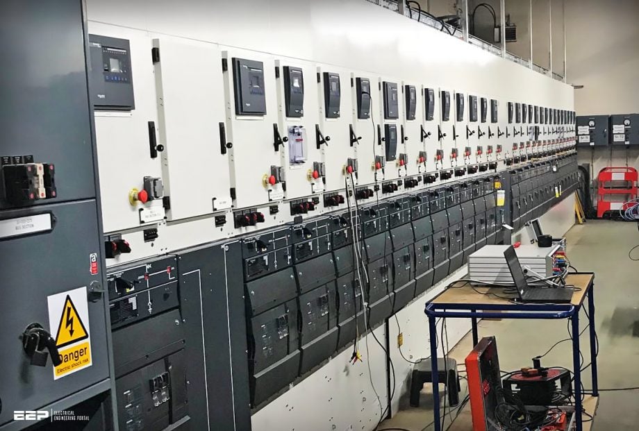
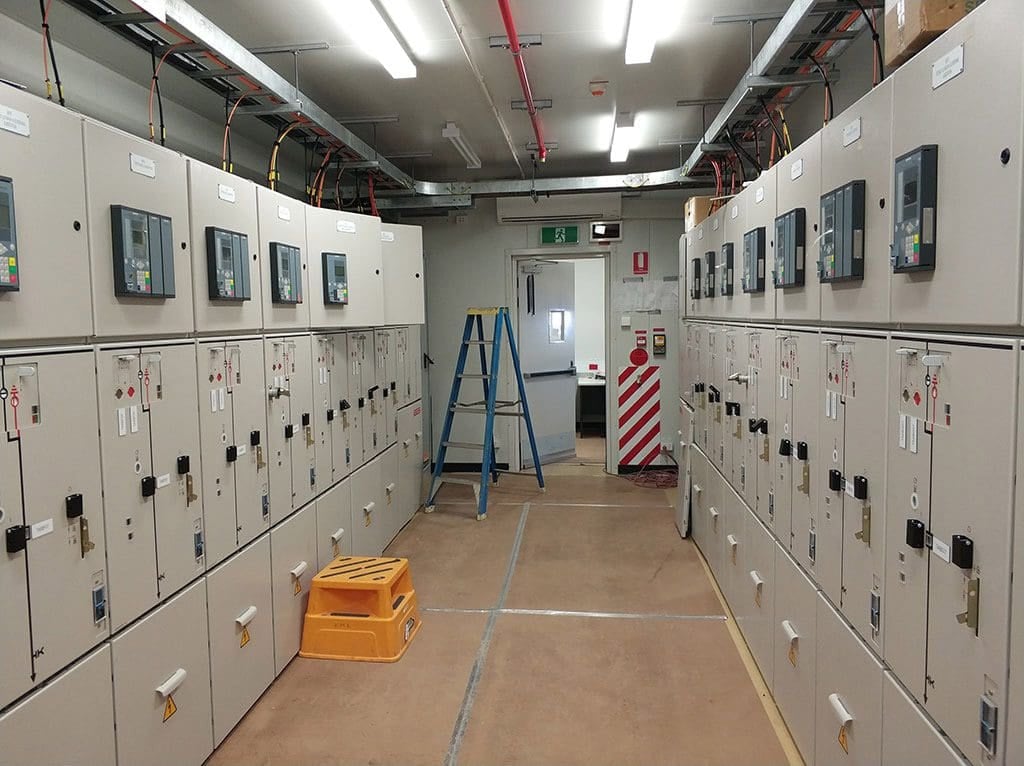
Indoor switchgear is normally of a metal-clad design. The various components forming the switchgear are arranged in compartments separated by earthed metal partitions. Thus we have a breaker compartment, CT/PT compartment, cable termination compartment, busbar compartment, surge suppressor compartment, LT busbar compartment, instrument panel chamber, etc.
Normally one set of busbars is used per switchgear and sometimes multiple busbars are used to ensure the reliability of the system in which case each busbar system must be accommodated in a separate compartment.
Metal-clad switchgear is built and tested in the factory with the complete assembly of the compartments and the entire unit is transported in one package. Metal-clad switchgear can be installed as a single independent unit or inboard formation. When these are used for individual control, a separate compartment for incoming cable and outgoing cables has to be arranged.
Figure 1 – Indoor metal-clad medium voltage switchgear
In the board formation, several switchgear are joined together in a row for different applications thus forming the complete board called a switchboard.
A complete switchboard has switchgear for different applications, e.g. incoming from the generator, station supplies from the grid, outgoing feeders for different applications, potential transformer panel for bus voltage/feeder voltage measurement and supply to voltage-dependent measurement/protection devices.
Regardless of whether switchgear is manufactured as a single unit or in switchboard formation, the end panels should be provided with suitable covers to prevent accessibility to HT and LT busbar/connections.
Go back to the Contents Table ↑
1.1.2 Outdoor switchgear
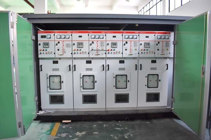
Outdoor switchgear is intended for installation in open space which is directly subjected to rain, dust and the environmental effects of the location. These can be mounted inside a metal enclosure in the form of kiosks for taking HT connections or mounted on a structure (porcelain-dad switchgear) or poles (pole-mounted) depending upon the application.
When metal-clad switchgear is to be installed outdoors, the enclosure has to be weather-proof.
Figure 2 – Outdoor medium voltage switchgear in a compact substation
Go back to the Contents Table ↑
1.2 Rating Considerations
Circuit breakers are rated at normal rated voltage and maximum operating voltage. This maximum operating voltage should not be exceeded by the power system to which the circuit breaker is applied. The circuit breaker rated current is the continuous current that it can carry without exceeding the temperature rise.
This is essential for the life of the insulation of the main power conducting parts!
Circuit breakers are normally rated for 50 or 60 Hz frequency. In special applications where the rated frequency is 200 Hz or above, the interrupting capability of the circuit breaker will be reduced.
Suggested Reading – Rating Definitions Applied to MV Circuit Breaker
Rating Definitions Applied to Medium Voltage Circuit Breaker
Go back to the Contents Table ↑
1.3 Ambient Considerations
MV switchgear is designed to operate successfully at the ratings specified on the rating plate under standard ambient conditions. Standard ambient conditions include a temperature of 40°C and an altitude up to 1000 meters. When these conditions change, the need for derating the switchgear arises. Also, the use of surge suppressors should be considered for all such high altitude installations.
In a circuit breaker, atmospheric air is used for both cooling and insulation. At high altitudes, the density of air is less resulting in poor cooling and poor insulation. Therefore, the derating of circuit breakers is to be considered.
The derating information is given in standards IEC62271-1 as well as in ANSI C37.04 (IEEE Standard for Ratings and Requirements for AC High-Voltage Circuit Breakers with Rated Maximum Voltage Above 1000 V). This derating information is available with manufacturers of switchgear, who offer it to users on request.
Good Reading – AC substation detailed design guidelines: Best practice, dos and don’ts
AC substation detailed design guidelines: Best practice, dos and don’ts
Go back to the Contents Table ↑
1.4 System Earthing Considerations
Both solidly grounded as well as ungrounded/non-effectively grounded systems are used for earthing. A solidly grounded system produces ground fault currents of sufficient magnitude to operate the earth fault relay of the affected feeder.
This leads to tripping of the correct circuit breaker and isolating the faulted portion of the system without interruption of power to the unfaulted portion.
Core balance current transformers (normally known as CBCTs) used in conjunction with sensitive earth leakage relays, or potential transformers with open delta secondary winding used in conjunction with neutral voltage displacement relay, help in the timely detection of these faults.
Suggested Course – Earthing and Grounding in Power Systems: Calculations, Design and Measurements
Earthing and Grounding in Power Systems: Calculations, Design and Measurements
Go back to the Contents Table ↑
1.5 Seismic Considerations
Initially, the concept of seismic withstand criteria was evolved for equipment used in nuclear power generating stations. But the human loss and the extensive property damage including heavy damages sustained by electrical equipment caused by major earthquakes in various parts of the world aroused widespread attention towards the need for the proper seismic design of equipment.
The different locations are classified into five zones on the basis of the seismic intensity for each of these locations. Verification is done by seismic testing which is performed on a shaker table, testbed or suitably constructed test fixture.
Important Reading – Substation and switchyard support structures for electrical equipment
Substation and switchyard support structures for electrical equipment (you SHOULD know)
Go back to the Contents Table ↑
1.6 Overvoltage Considerations
Surge suppressors (also called surge arrestors) are used to protect electrical equipment such as transformers, motors, capacitor banks against the system overvoltages or over-voltages developed due to a particular type of switching medium employed.
Commonly used surge suppressors are the capacitance-resistance combination type of surge suppressors and gapless zine oxide surge suppressors.
Related Course – Transformer Differential Protection Course: Understanding Schematics, Relay Settings and Testing
Transformer Differential Protection Course: Understanding Schematics, Relay Settings and Testing
Go back to the Contents Table ↑
2. Application of Switchgear in Power System
switchgear are necessary at every switching point in the power system. Some of their applications are given below
2.1 Generator Circuit Breakers
Generator circuit breakers are installed between the generator and the transformer. These are indoor switchgear. These breakers are required to interrupt the very high fault current of the generators and the operating speed for fault clearance has to be very high (within four cycles).
This rapid clearance of the fault current helps to avoid expensive damage to power plant equipment and consequently long downtime for repair. The design of the circuit breaker becomes highly complicated due to this requirement.
Another new development has been the integration of all the associated items of the switchgear such as series disconnector, earthing switches, short-circuiting switches, current transformers, single-pole-insulated voltage transformers, protective capacitors and surge arrestors, within the generator circuit breaker enclosure as an option to separate installation.
The typical ratings of the generator circuit breakers are given in Table 1.
Related electrical guides & articles


Edvard Csanyi
Hi, I'm an electrical engineer, programmer and founder of EEP - Electrical Engineering Portal. I worked twelve years at Schneider Electric in the position of technical support for low- and medium-voltage projects and the design of busbar trunking systems.I'm highly specialized in the design of LV/MV switchgear and low-voltage, high-power busbar trunking (<6300A) in substations, commercial buildings and industry facilities. I'm also a professional in AutoCAD programming.
Profile: Edvard Csanyi
