
Estimated Study Time: 18 minutes
Control harmonic techniques
The first technique to control harmonic-related problems in the industry involved substantial use of single-tuned filters to offer a low-impedance path to harmonic currents. Interestingly, it is not difficult to find harmonic-producing loads in the megavolt-ampere range in the industry operating with no harmonic filters. This is a difficult issue for power utilities to control because the existing standards are often more of a reference guideline for the industry than a regulatory pronouncement.
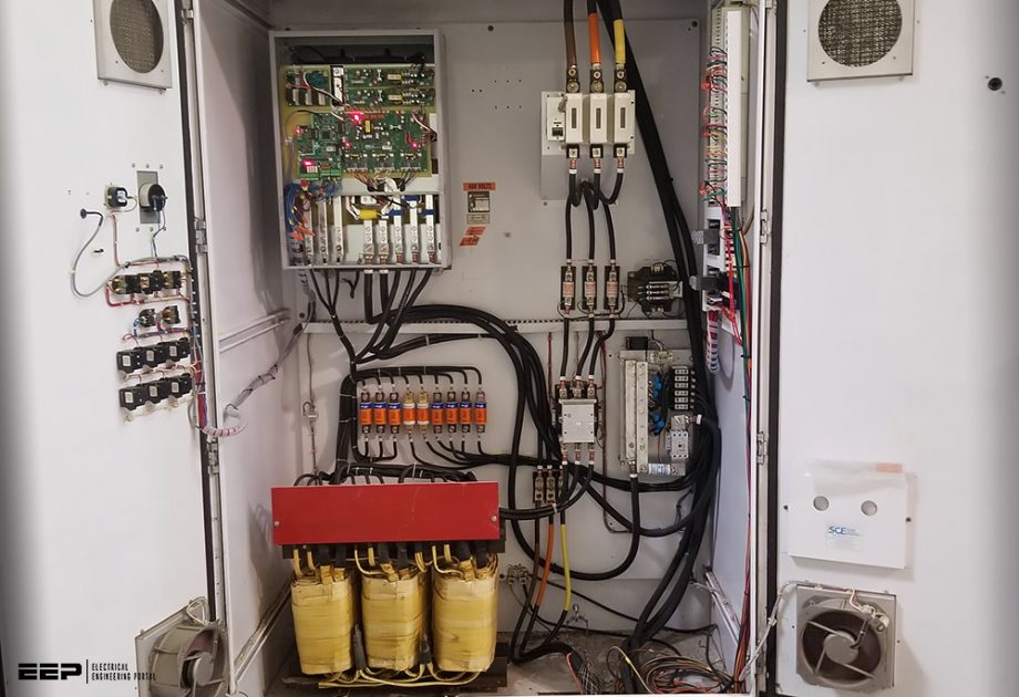 Six methods to control the flow of harmonic currents and decrease harmonic distortion limits (on photo: Retrofit of a Benshaw SG Series VFD with a new diode rectifier on an existing 18 pulse system; credit: @SwitchgearSol)
Large harmonic producers, typically in the industrial sector, may be the only producers who adopt harmonic filtering methods to reduce the otherwise multiple disturbances that may arise beyond the metering point and start affecting sensitive equipment and processes. Due to the high cost involved, this is not a common practice in commercial and residential facilities.
Unfiltered harmonic currents are left to spread freely upstream and downstream from the PCC following natural laws of propagation. They may reach adjacent installations and sometimes may even make their way to the utility substation.
It is then common to see utilities and harmonic-producing customers in a continuous search for alternative methods to handle and hopefully beat elevated harmonic distortion levels.
Notice that harmonic currents on the source side of the converter are by no way controlled or eliminated in the windings. Some cancellation of harmonics can take place, for instance, in phase-shift transformers that provide 30° shifting between two six-pulse converters: one fed from delta-connected and the other from wye-connected secondary windings of the transformer.
This technical article describes some of the techniques used in industry to control the flow of harmonic currents produced by nonlinear loads in power systems. The most relevant are the six following:
- Network reconfiguration
- Increase of the short-circuit current ratio
- Static multipulse power converters with phase shift transformers
- Series reactors
- Phase load balancing
- Load grouping
1. Network topology reconfiguration
One measure often advantageous to reduce the effect of unfiltered harmonics is the reconfiguration of the network. Here it is necessary to identify users and sectors in the installation that introduce large amounts of harmonic currents to the system and to characterize its frequency content.
As often occurs in residential installations, redistribution of loads using the same wiring or through additional circuits can provide an economic solution for drastically reducing disturbances.
If harmonic filters are not an option to consider, mixing linear and nonlinear loads on a feeder may allow the reduction of harmonic distortion because linear loads act as natural attenuators of parallel resonant peaks. This measure should not be contemplated when linear loads comprise sensitive electronic or industrial processes, which may be disrupted if THD at some point is somewhat increased.
Suggested reading – Guidelines for selecting the proper VFD for motor applications
Guidelines for selecting the proper Variable Frequency Drive (VFD) for motor applications
Go back to the Contents Table ↑
2. Increase of supply mode stiffness
The increase of the ratio between the available short-circuit current and rated load current makes a stronger supply node. This happens whenever power utilities increase their substation’s size. It also occurs when industrial customers add some cogeneration on the supply bus to help operation during peak demand.
Stiff AC sources increase the available short-circuit current, for which the ratio between short circuit and load currents is often used as a measure of source stiffness. Strong supply nodes can better absorb transient disturbances in the network and attenuate the effects of large transformer inrush currents, cable energization, and the start of large motor loads.
High short-circuit currents are then associated with low impedance sources, which are in turn inverse functions of transformer size. This can be illustrated by calculating the change of impedance when an “old” transformer of rating MVA1 is replaced by a “new” transformer rated MVA2.
By using the fundamental expression for transformer impedance described in Equation (1):
we arrive at the following:

If we assume all other parameters the same, the impedance ratio in Equation (7.2) reduces to:

That is, the impedance ratio of a new to an old transformer varies with the inverse ratio between the old and the new transformers’ megavolt amperes. For instance, a 30-MVA transformer would present an impedance twice as small as a 15-MVA transformer of the same voltage class and a two-times increase in short-circuit current, assuming the two of them have the same leakage impedance.
At harmonic frequencies, inductive and capacitive impedances of the system vary as a function of frequency:
![]()
A stiffer source will primarily affect the inductive component of the system. Harmonic currents will produce voltage drops affected by the inductive reactance of the system, which is composed of feeder and substation components.
For the case of short feeders, the source impedance will be the dominant component. In these situations, harmonic currents are likely to reach the substation and the voltage drop on the source impedance, and thus the harmonic distortion will be smaller in stiffer systems.
Go back to the Contents Table ↑
3. Harmonic cancellation through use of multipulse converters
One-phase converters are used in small-load applications. For lower initial costs, half-wave rectifiers can be applied when current requirements are small. Half-wave rectifying produces a DC component that saturates transformers. To limit the former, the use of full-wave rectifying converters is recommended.
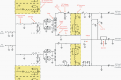
A basic polyphase converter is a six-pulse unit. Theoretically, the 12-pulse unit shown in Figure 1(a) will eliminate the lower order harmonics (5th and 7th), for which the first harmonics that will show up are the 11th and the 13th. Because the 17th and 19th are not characteristic harmonics, the following harmonic pair to appear will be the 23rd and the 25th.
Figure 1a – Phase-shift transformer connections for 12-pulse converters
Through additional phase multiplication, it is possible to reduce other harmonic currents. For instance, a 24-pulse unit is built up from four 6-pulse rectifier bridges, each of which has a phase shift of 15° relative to the other rectifying units. This is attained by using phase-shifting transformers with separate additional windings connected in zig-zag or in a polygon, as illustrated in Figure 1(b).
If a six-pulse unit were out of service, some cancellation would still be established with two of the six-pulse units 15° out of phase to one another. However, the third unit would show all of the harmonics typical of a six-pulse converter in the system.
Figure 1b – Phase-shift transformer connections for 24-pulse converters
The conditions for eliminating harmonics on a six-pulse rectifier composed of N sections using the phase multiplication approach are the following:
- The transformers involved are all of the same transformation ratios and have similar leakage impedances.
- The load is split in like parts among the converters.
- The firing angle is the same in all converters.
- The phase difference between transformers is 60/N electrical degrees.
The characteristic harmonics of this harmonic reduction scheme can be expressed as follows:
![]()
where:
- h is the harmonic order.
- q is equal to 6 × N.
- N is the number of six-pulse rectifiers.
- k is an integer number (1, 2, 3, …).
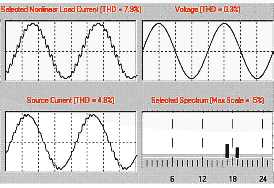
Figure 2 describes voltage and current waveforms at load and source locations, along with the harmonic spectrum of the 18-pulse converter.
Go back to the Contents Table ↑
4. Series reactors as harmonic attenuator elements
Series reactors have been used in industry for a long time as a way to provide some control on short-circuit current levels. We see them in iron and steel or smelting plants and in power substations or neutral-to-ground connections of generators or power transformers. Series reactors are to some extent also used as harmonic attenuators in industrial applications.
Typically, 5% impedance reactors installed on the source side of power converters are seen in a number of applications.
This looks attractive as a way to provide some relief to transient or subtransient types of events on the power line side created during switching of capacitors banks or long cables or transient disturbances created during line faults, in addition to the attenuation of harmonic currents.
Figure 2 – Eighteen-pulse rectifier
Go back to the Contents Table ↑
5. Phase balancing
Some electric power companies use four-wire distribution systems with a primary grounded wye and single-phase transformers supplying phase to ground voltage to single-phase loads such as residential installations, municipal street lighting, etc. Variations in single-phase loads can create unbalanced currents in three-phase conductors, producing dissimilar voltage drops in the three phases and giving rise to phase-to-phase voltage unbalance.
Maximum phase-to-phase or phase-to-ground voltage unbalance may be more critical at the far end of a distribution feeder, where voltage may have experienced a substantial drop during heavy load conditions — particularly in the absence of appropriate voltage profile compensation measures.
A perfectly balanced system is difficult to attain because single-phase loads are constantly changing, producing a continuous unbalance of phase voltages and eventually causing the appearance of even and non-characteristic harmonics.
Suggested reading – Balancing of single-phase loads to achieve energy efficiency
Balancing of single-phase loads to achieve energy efficiency
Go back to the Contents Table ↑
5.1 Phase voltage unbalance
The simplest method to determine voltage unbalance is by calculating the greatest deviation of the phase-to-phase voltage from the average voltage as follows:

For example, if a 480-V application shows voltages VAB, VBC, and VCA equal to 473, 478, and 486 V, respectively, with an average voltage of (473 + 478 + 486)/3 = 479 V, the voltage unbalance is as follows:

The amount of voltage unbalance can also be expressed in terms of the negative sequence voltage:

Go back to the Contents Table ↑
5.2 Effects of unbalanced phase voltage
When the unbalanced phase voltages are applied to three-phase motors, they give rise to additional negative sequence currents that will circulate in the motor windings, increasing heating losses. The most severe condition occurs under an open-phase situation.
All motors are sensitive to unbalance in the phase voltage. Certain kinds of motors, like those used in hermetically built compressors in air-conditioned units, are more susceptible to this condition. These motors operate with elevated current densities in the windings due to the aggregate effect of refrigerant cooling.
When a motor is suddenly shut down by the protective system, the first step consists of determining the cause of the disconnection and checking the operation current after it has been put back into operation, to make sure that the motor is not overloaded. The next step consists of measuring the voltage in the three phases to determine the amount of voltage unbalance.
In general, one-phase loads ought not to be connected to three-phase circuits that provide power supply to sensitive equipment. A separate circuit should be used for that purpose.
Figure 3 – Derating factor for motors with unbalance in the phase-to-phase voltage
Go back to the Contents Table ↑
6. Load grouping
Extensive electric networks may have nonlinear loads with different spectral content. Whenever possible, grouping loads by type of harmonic spectrum (for instance, 6-pulse converters, 12-pulse converters, arcing type devices, fluorescent lighting, etc.) can optimize the installation, location, and sizing of harmonic filters.
Load grouping could also help reduce telephone interference by trying to keep telephone lines as distant as possible from sites carrying higher-order harmonic currents.
Suggested reading – Protection of three-phase motors from unbalance (loss of phase and phase rotation)
Protection of three-phase motors from unbalance (loss of phase and phase rotation)
Go back to the Contents Table ↑
Source: Harmonics and power system by Francisco c. De La rosa
Related electrical guides & articles


Edvard Csanyi
Hi, I'm an electrical engineer, programmer and founder of EEP - Electrical Engineering Portal. I worked twelve years at Schneider Electric in the position of technical support for low- and medium-voltage projects and the design of busbar trunking systems.I'm highly specialized in the design of LV/MV switchgear and low-voltage, high-power busbar trunking (<6300A) in substations, commercial buildings and industry facilities. I'm also a professional in AutoCAD programming.
Profile: Edvard Csanyi

The article successfully describes how we can manage harmonuc issues without installing APF’s or STSTCOMS to certain extent