
Estimated Study Time: 7 minutes
Introduction
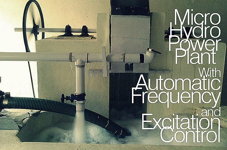
First of all, I am very glad to say that our project was successful. It is hydro power plant which was completed totally by our five members team namely me, Chitransh Shrivastava, Akshay Tiwari, Pranjan Lele, Pankaj Sonwane and special thanks to Mr. Arvind Solanki.
Our motive for making this prototype is to express the load and demand factor with their relative changes in practical manner, because an electricity consumer can’t go in any generating plants.
Its controlling panel is same for thermal power plant, and it have all the section same as the real power plant.
Initially we decided that what amount of electrical power we need to generate after then we can make a profile of plant. We decided 2.5kw generation (which is sufficient for two rooms) according to this we created pelton wheel turbine from its drawing to fitting on the shaft.

So for this prototype, we started this project with mentioned below steps.
- Site selection.
- Civil construction.
- Aligned to bearing with turbine shaft.
- Coupled the shaft to Synchronous Generator.
- Input power through Monoblock motor.
- Pipe line or penstock with subsequent jet.
Control of Excitation and Frequency of the Synchronous Generator has become the most important consideration in the generating plants. Synchronous generators are used almost exclusively in power systems as a source of electrical energy.
The primary reason for accurate frequency control is to allow the flow of alternating current power from multiple generators through the network to be controlled. The trend in system frequency is a measure of mismatch between demand and generation, and so is a necessary parameter for load control in interconnected systems.
Frequency of the system will vary as load and generation change. Increasing the mechanical input power to a synchronous generator will not greatly affect the system frequency but will produce more electric power from that unit. During a severe overload caused by tripping or failure of generators or transmission lines the power system frequency will decline, due to an imbalance of load versus generation.
Loss of an interconnection, while exporting power (relative to system total generation) will cause system frequency to rise.
For satisfactory operation of a power system, the frequency should remain nearly constant. Relatively close control of frequency ensures constancy of speed of induction and synchronous motors.
Constancy of speed of motor drives is particularly important for satisfactory performance of generating units as they are highly dependent on the performance of all the auxiliary drives associated with the fuel, the feed-water and the combustion air supply systems. In a network, considerable drop in frequency could result in high magnetizing currents in induction motors and transformers.
The extensive use of electric clocks and the use of frequency for other timing purposes require accurate maintenance of synchronous time which is proportional to integral of frequency. As a consequence, it is necessary to regulate not only frequency, but also its integral.

The frequency of a system is dependent on active power balance. As frequency is a common factor throughout the system, a change in active power demand at one point is reflected throughout the system by a change in frequency. A speed governor on each generating unit provides the primary speed control function, while supplementary control originating at a central control center allocates generation.
In an interconnected system, with two or more independently controlled areas, in addition to control of frequency, the generation within eacharea has to be controlled so as to maintain scheduled power interchange. The control of generation and frequency is commonly referred to as load-frequency control (LFC).
The generator is supplied with real power from a prime mover, usually a turbine, whilst the excitation current is provided by the excitation system.
The basic function of an excitation system is to provide direct current to the synchronous machine field winding.
In addition, the excitation system performs control and protective functions essential to the satisfactory performanceof the power system by controlling the field voltage and thereby the field current. The control functions include the control of voltage and reactive power flow, and the enhancement of system stability. The protective functions ensure that the capability limits of the synchronous machine, excitation system, and the other equipments are not exceeded.
Conclusion
The problem of power system dynamic stability has received growing attention over the last decades.
The main reason for this is the increasingsize of generating units and the use of highspeed excitation systems. The effect of the high-speed excitation on dynamic stability is to add negative damping to the system thereby causing oscillations with weak damping.
A design of such an excitation system should also be satisfactory for a wide range of operating conditions as well as for fault conditions. Practical methods fornonlinear control include an open-loop inverse model of the nonlinear plant dynamics and the use of feedback loops to cancel the plant nonlinearities.
The approximation of a non-linear system with a linearized model yields to the application of adaptive control, where real-time measurements of the plant inputs are used, either to derive explicitly the plant model or design a controller based on this model (indirect adaptive control) or to directly modify the controller output (direct adaptive control).
Related electrical guides & articles


Aakash Johari
Hi, I am fresher Electrical & Electronics Engineer belongs from indore (india ). My interest is so much inclined towards the new project work and innovations in electrical field i had also done some projects with my friends... To be a part of this portal i want to enhance my knowledge and then contribute my domain experience.... Thankyou.. :)Profile: Aakash Johari

Needs more articles in relation with my thesis project as 20kw microhydro power plant. And one of my concern is on how to prevent the system in a stage of overvoltage and under voltage stages where might cause in the system to become abnormal operation. And would it be possinle to add a storage battery bank to be use as additional supply during peak load?
hi,.
you can use electronic load controller ,for your micro hydro power plant,.and can maintain the frequency rpm there by voltage,.
mail me for more information
[email protected] cell +91 9445125622
http://dhavamanitechnologies.blogspot.in/
Give me your mail id
For stability you may want to consider a flywheel for increased inertia.
Great
Hello Mr. Akash Johari ,
i am kailash chouhan (Mechanical) i started a project which is based on pelton wheel but my work is not complete due to lack of resource i need to use the bucket of pelton wheel to complete my project but after surveying for making pattern is to expensive to me.so if it is possible please arrange this runner
Thank you
Thanq sir for good information..
chiricahua apache nation member
looking for a water hydro power 3 phase output power
to install into a water tower to supply head pressure down into turbine
Nice article
What is your opinion of Tesla turbines? I am working on a solar-steam system sized for residential solar thermal systems, and was planning to use a Tesla turbine for it’s simplicity of manufacturing. Thank you for any input.
-Anthony.
Hi:
I’m keen to know the part where you say you have synchronized to the grid. Did you transmit the power to the Grid or just provided the power to light the lamps. What was the type of Alternator used and what is its RPM. I would like to discuss this with you more. My email id is ramaswami2000 at gmail dot com please get in touch me.
Thank you Aakash. My doubt is cleared from your explanation.
As a matter of fact, I am too impressed from this website.
Could you please send me some projects as an idea so that even I can try it out and let you know the output of it. As i am very much interested in Electrical Engineering, I wish to concentrate more and work on Controls and Automation related sector. Can you just help me out in such things so that i can improve my knowledge? Just drop me the related documents and related websites for reference as a mail to [email protected].
Thank you very much… :)
So, I have read the article relating the MICRO HYDRO POWER PLANT which was very interesting. I use to read every article posted each time. i am very very much impressed by this website. I am thankful to someone who introduced this site to me.
I have some doubt in this article. The thing is that the pelton wheel is used in this project as the excitation purpose. Why is that the pelton wheel turbines are used have cup structured models. Why can’t the ends of the pelton wheel be flat so that the water through the nozzles can hit it in a maximum force and the wheel could rotate faster. I understand that it may spread water outside. But could it be effective if a flat structured model of a pelton wheel is used???
Hi Jegadeesh,
As you mentioned your doubt about the designing of pelton wheel
turbine so, its bucket or cup designing is plays most important role
for efficient power flow because When the water-jet contacts the
bucket, the water exerts pressure on the bucket and the water is
decelerated as it does a “u-turn” and flows out the other side of the
bucket at low velocity. In the process, the water’s momentum is
transferred to the turbine. This “impulse” does work on the turbine.
For maximum power and efficiency, the turbine system is designed such
that the water-jet velocity is twice the velocity of the bucket. A
very small percentage of the water’s original kinetic energy will
still remain in the water; however, this allows the bucket to be
emptied at the same rate it is filled, (see conservation of mass),
thus allowing the water flow to continue uninterrupted. Often two
buckets are mounted side-by-side, thus splitting the water jet in
half. This balances the side-load forces on the wheel, and helps to
ensure smooth, efficient momentum transfer of the fluid jet to the
turbine wheel.
hi Aakash, My interest is so much inclined towards the new project work and innovations in electrical field same as you ,so please tell me most difficult and innovative projects,friend give me reply fast because i have to submit its details to my sir with in 7 days