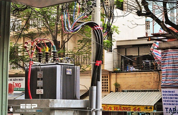
Why Mineral oil?
As you already know, this is the most common type of distribution transformer. It is one of the most important part and can be found on electrical supply systems in every country of the world.

Although the insulating oil is a flammable liquid, the reliability of the oil-immersed transformer has been proven over many years on supply systems where security of supply is of the utmost importance.
However, mineral oil is flammable and although most fault conditions that occur within the windings of a transformer result in no more than a discharge of oil, it is possible, particularly when an electrical arc occurs just below the surface of the oil, for it to be ignited.
For this reason oil-immersed distribution transformers are usually positioned outside buildings within a suitable fence enclosure or in separate brick-built buildings away from personnel.
However, the additional costs of the civil engineering work required can make the installation of a mineral oil-filled transformer uneconomic.
In these instances, a dry-type transformer, or a transformer filled with a high fire-point liquid, is often selected for the installation. The integrity of the insulation system of an oil-immersed transformer relies partly on the condition of the oil. It has been common practice on most established supply networks in the world to let transformers breath naturally as the insulating liquid expands and contracts with load.
However, it has also been recognised that some form of protection system that prevents the contamination of the liquid by air-borne pollutants has the advantage of a longer insulation life, particularly when load factors are high.

The simplest form of oil protection system, which is perfectly adequate for most installations of distribution transformers below 500 kVA installed in the temperate zones of the world, is a silica-gel dehydrating breather.
Here, the air drawn into the transformer tank during reduced load conditions is passed through an oil bath, to reduce solid contaminants, and then through the dehydrating crystals of silica-gel to remove the moisture.
Probably the most common form of oil protection system is found with the conservator or expansion vessel; this has a sump which traps most air-borne pollutants (Figure 1 above).
The most obvious method of eliminating oil contamination is to seal the tank from the outside air and design it to tolerate the pressures developed by the expanding liquid coolant (Figure 2). Because of gas solubility in oil these pressures are never very high and rarely exceed 0.43 kg/cm2 under steady load conditions.
The development of special machinery which automatically folds and welds the steel plate into deep corrugations to form the transformer tank side, has allowed the corrugated tank to become more cost effective. The steel plate is usually between 1.2 and 1.5 mm thick, resulting in a tank which is both light and compact, the mechanical strength being obtained by the deep closely-spaced corrugations.

Plate widths of up to 2000 mm and depths of 400 mm allow transformers of up to 5000 kVA to be cooled by this method, but their general application is in distribution ratings of up to 1600 kVA.
The ability of the corrugated panels to flex has enabled the development of the fully sealed corrugated tank design. In this instance the tank is completely filled, expansion of the liquid being accommodated by flexing of the tank walls. The liquid within the tank has no contact with the atmosphere, which assists with the preservation of the transformer insulation system, as well as reducing the maintenance requirements.
Corrugated transformer tank designs have been in service for in excess of 30 years and are now established as a reliable method of tank construction.
Distribution Transformer (VIDEO)
Reference: Handbook of Electrical Installation Practice – Eur Ing GEOFFREY STOKES


We are the leading transformer manufacturing Sri Lanka for over 4 decades. joint venture between Sri Lanka electricity Board.
Thanks for a sharing the useful information. This blog information is real knowledge.
What are the differences between mineral oil, silicone and the new FR3 insulating fluids used in power transformers today?
Could any one tell the alternate of Mineral Oil Used in Voltage Transformers.Any replacement by synthetic oil which is more relible and less hygrscopic less contamination, low maintenance etc.
Dear Sir
What is the thickness of each lamination used for making the magnetic core. is it 0.3 mm to o.5 mm for 50 Hz or less. If it less, the core vibrations and mechanical strength problems. Anything to overcome the problems.
Pls reply
Good morning, Sir Edvard
I would like to ask some question if it is possible to connect the two transformers protection accessories in parallel,if the two transformer are connected in the same feeder or VCB?.If the old transformer are lack of protection accessories than the new ,and they are of different brands.
Hoping for your immediate response.
Best Regards:
R.B.Dalina
Pls give suggestions and examples for Ex proof and Weather proof electrical systems.