
Estimated Study Time: 26 minutes
LV design mistakes & consequences
To provide the end user with a safe, effective, and reliable solution, a designer must steer clear of numerous blunders and misconceptions when creating a low voltage distribution design. Although there are many misconceptions about electrical designs, the ones I’ll mention in this article are frequent and likely to occur because of costs and a failure to adhere to the rules and regulations.
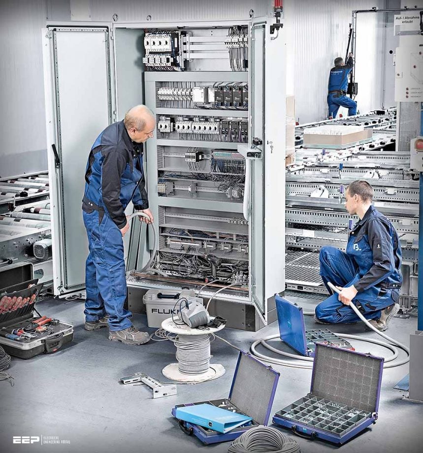 Ten biggest mistakes and misconceptions in the design of low voltage distribution systems (photo credit: blumenbecker.com)
Therefore, in this article, you will learn how to avoid such mistakes using the proper cost-saving technique without deviating from the standards and codes. Moreover, we will also understand the importance of using some design programs that will improve the quality of the electrical design, such as the lux calculation program DIALux, which contributes to the design of efficient distribution of light fixtures evenly.
After you learn about common mistakes in the low voltage design, you may want to learn more about how to design a complete low voltage distribution design project from scratch by enrolling in my course bundle “Electrical Low Voltage System Distribution Design” video-based course and coursebook through the following link.
- Wrong Selection of Electrical Rooms
- Missing Spare Circuits in Distribution Board (DB) Schedules
- Unbalancing Loads in DB Schedules
- Random Distribution of Light Fixtures
- Ignoring Furniture Layout during the distribution of power sockets
- Ignoring Spare Space for Cable Trays & Trunks
- Not Using Panels Technical Sheets as Reference
- Disregarding Cost Saving in the Design
- Ignoring Roof Isolators for Outdoor Units
- Ignoring to specify Cable Type in the Design
1. Wrong Selection of Electrical Rooms
The selection of electrical rooms for any project must be made in the early stages of the design, specifically when the architect of the project designs the architectural layout. Selection of the suitable location of electrical rooms is a critical task and must be done considering different aspects of the design. For example, easing the cable routing will contribute to saving costs.
There are some questions that, if answered, will contribute to the selection of the most appropriate location for an electrical room:
- Can the selected room accommodate the number of panels and electrical boards?
- Is the room located nearby a hazardous area where fire or explosion may occur?
- Is the main electrical room located nearby the transformer room?
- Is the room located in an area that could serve the entire floor without obstructions?
To ensure that the chosen electrical room location could serve other electrical rooms of the project with a straight pathway without changing its routing.
Therefore, an electrical designer must look at the staircases and elevator shafts and select the adjacent rooms. Choosing an electrical room adjacent to the stairs on the ground floor of the building, for instance, will guarantee the selection of other electrical rooms on the upper floors of a building to be at the same location.
This will result in an easing of the cable routing between distribution panels throughout all the floors of the building.
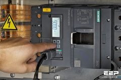
Figure 1 – Electrical distribution panels installed in an electrical room

On the contrary, some electrical designs do not provide convenient locations for electrical rooms, like selecting the room nearby a wet area which might expose the electrical panels to direct contact with water causing hazardous situations. Additionally, electrical rooms may be located under staircases which does not provide enough space to accommodate future panels, and the accessibility for maintenance becomes problematic.
A project may include one or more main panels that serve several sub-main panels located on each floor to feed distribution boards at each level. Selecting an electrical room beside a staircase or elevator shaft, always continuous up to the roof floor, will be the easiest and shortest way to connect cables between panels.
The electrical name of this opening is a “riser,” which is an opening in the concrete slab to provide a continuous way for electrical feeders to all building floors.
Figure 2 – Electrical riser for cable trays and trunkings
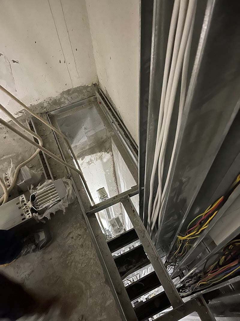
Figure 3 – Electrical riser design drawing

Go back to the Contents Table ↑
2. Missing Spare Circuits in DB Schedules
One of the biggest mistakes that electrical designers must avoid is not adding spare circuits to Distribution Board (DB) schedules. The probability of adding loads at any time is always potential. Therefore, instead of adding a new distribution board to feed the additional load, having spare circuit breakers will ease this process.
The recommendation for spare circuits is 25% of the total loads. For example, a three-phase DB schedule 12-way type would have four ways as a spare. Four ways of spares mean the user can connect up to 12 additional single-phase loads. Each way represents three circuits R, Y, and B, meaning the user can connect both single and three phases according to the connected load type.
For example, a three-phase circuit breaker is required instead of a single-phase ELCB instead of MCB, etc. As a result, electrical designers could indicate the additional 25% circuits as “spares” and “spaces” for practical purposes during the addition of loads to the connected DB.
The below figure shows a 12-way DB schedule with an additional 25% of spares and spaces.
Figure 4 – Distribution board (DB) schedule spares and spaces (click to zoom)
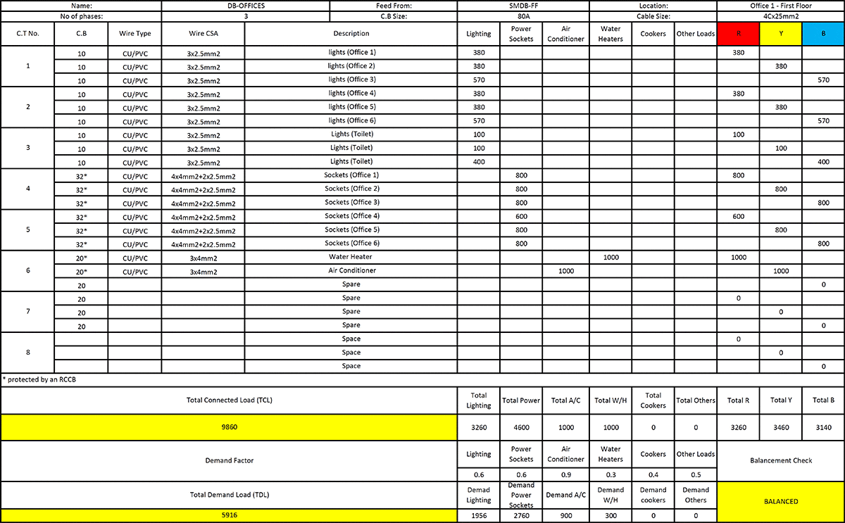
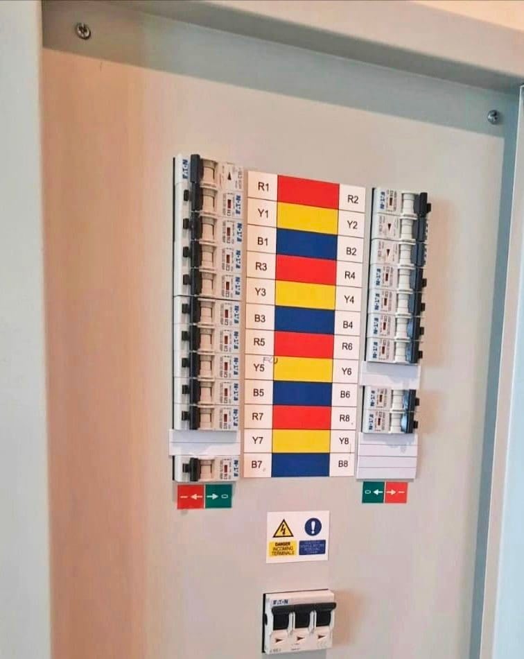
You will notice that the additional “spare” circuit breaker is indicated with its rating ampere because they will have to be installed inside the DB during execution stages at the site. Note that “spaces” are just left as blanks to indicate that no breaker is needed to be installed and it is left for the end user’s decision according to the connection type of load.
The below figure shows what spaces of a DB look like after being covered with dummy lids for safety and not to allow dust and insects to enter the DB.
Figure 5 – Blank cover used in distribution board for space circuits
Go back to the Contents Table ↑
3. Unbalancing Loads in DB Schedules
In a three-phase system, it is crucial not to ignore the balancing of loads. This mistake will affect the whole system’s efficiency and might cause severe consequences, as explained in the following lines. So, after defining the loads and adding them to the DB schedule to obtain the demand and total connected load in a three-phase system, it is imperative to balance the loads.
In other words, in a three-phase system, there are Red, Yellow, and Blue phases that are connected to single and three-phase loads and are distributed between them.
Related electrical guides & articles


Mohammed Ayman
I earned my degree from Eastern Mediterranean University (Turkey, North Cyprus) in B.S Electrical & Electronic Engineering; shortly after, I began my career as an electrical site engineer in a mega-scale project in Qatar which allowed me to monitor and supervise electrical site installations. I indulged in the design field of the electrical low voltage distribution systems and have accomplished more than 10 projects with the compliance of the national codes & international standards.Profile: Mohammed Ayman
