
Estimated Study Time: 16 minutes
Single line and wiring diagrams
In order to create a consistent and technically correct single line or wiring diagram, more than basic knowledge about the engineering field in question is required. Besides electrical installation and equipment, the design engineers should be familiar with electrical symbols and software packages for drawing.
 Eight common mistakes in reading and creating single line and wiring diagrams
This is a good moment to mention that diagram design and diagram drawing are basically two separate activities, especially in the case of more complex switchboards and installation. The first one requires adequate engineering skills and experience for equipment dimensioning and proper functionality of the whole installation, hence a higher level of responsibility is involved. The second one can be done by a skilled technician, sometimes called a draftsman, if all components and connections are already chosen, i.e. designed.
Practically the same, except maybe necessity for drawing software, stands for diagram reading.
Again, understanding of graphical presentation on one side, and the ability to check diagram compatibility with calculations and standards on the other side, are two different things.
As I wrote in one of my previous articles, called How to read single line and wiring diagrams, single line diagrams are simplified and digest picture of the whole switchboard, showing only major power equipment and connections to other switchboards. Wiring diagrams are used to show the control, measurement, and signalization principle of operation inside the switchboard.
Within this article, full engineering approach to single line and wiring diagrams creation and reading will be presented. That means both, design and graphical presentation.
As already started within the above mentioned previous article, some most important and most often mistakes during this process will be described. Of course, the goal is to avoid these mistakes whenever is possible and create a correct and usable single line or wiring diagram.
Description and examples of typical mistakes:
- Lack of design tags
- Inconsistency of design tags
- Lack of most important textual and numerical data
- Incorrect graphical representation
- Lack of connections to other switchboards and devices
- Incorrect wiring
- Lack of cross references
- Lack of comments and clarifications
Description and examples of typical mistakes
Here are some common mistakes which can be found in a single line and wiring diagrams, according to my so far gained experience. If you design and/or draw this kind of diagram, try to incorporate details and principles illustrated below into your document.
If you read a diagram created by someone else, try to pay attention to these basic rules, and if there is a mistake noticed, try to correct it, or at least avoid mistakes in further project stage which may be caused by it.
1. Lack of design tags
Design tags are necessary to be used if we want every electrical component to have its own unique graphical presentation. And we want that.
Figure 1 shows an example of this mistake, and how it can be corrected.

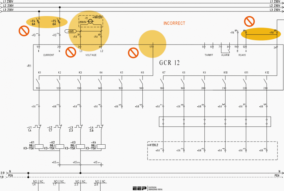
2. Inconsistency of design tags
As we mentioned above, design tags shall provide a unique graphical presentation of each component that is used, but not only that. The principle of design tag creation shall be the same within the project, and the same letter symbol is advisable to be used for components of the same type.
For example, Q is usually used for circuit breakers, F for fuses, M for motors, W for cables, etc. Nowadays, =FUNCTION +LOCATION -PRODUCT principle for creation of project tag for equipment is recommended, according to IEC 81346.
When we want to assign a tag for a product, i.e. component, the use of sheet number on which component can be found inside diagram can be very useful, especially in the case of more complex diagrams and a larger number of drawing sheets.
Whichever principle for project tag creation is chosen by the design engineer or draftsman, it is important to be consistent. Inconsistency can lead to unclear technical documentation and increase the possibility of other mistakes during the project realization.
Figure 2 shows an example of this mistake, and how it can be corrected.
Related electrical guides & articles


Miodrag Kokotovic
Graduated from Faculty of Electrical Engineering, within University of Belgrade, in the field of electrical power systems. Expert in electrical part of tender preparation, design, procurement, construction and commissioning of treatment plants and pumping stations, electrical power quality and energy management.Profile: Miodrag Kokotovic
