
Estimated Study Time: 14 minutes
Basics about the subject
Power factor correction (PFC) and reactive power compensation (RPC) are often used as synonyms in practice. Although they are similar and mutually dependent terms, they don’t represent the same thing. RPC is a procedure for reducing total reactive power of some consumer(s), usually by adding capacitive load in the form of power capacitors to already existing reactive load which is inherently inductive.
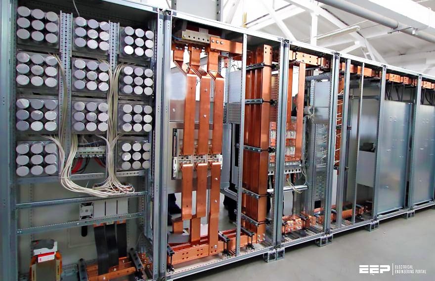 How to avoid common mistakes during wiring and startup of power factor correction (PFC) cubicle (on photo: Rear side of LV switchgear with wired power factor correction cubicle; credit: Engineering company 'B&S')
This procedure, if other relevant load parameters remain the same, will result in PFC, but latter, which simply means increasing of load power factor, can also be achieved by some other means.
For example, if active power is increased while reactive power remains the same, power factor will be increased as well. Similarly, power factor is also dependent on electrical machine’s load factor (actual load divided by rated load value).
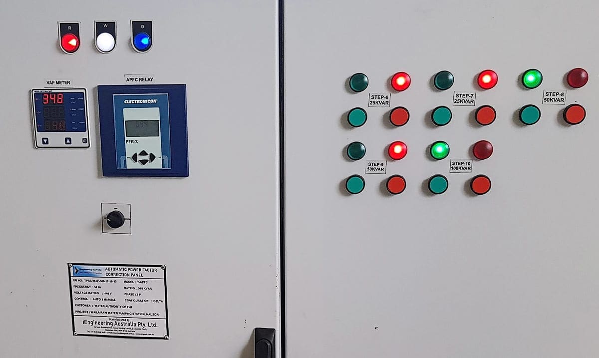
Electronic regulator is the brain of automatic PFC operation. By “automatic” we assume regulation of connected reactive load caused by compensated load variation, independently of measurements or switching operations carried out by operator. This regulation is usually stepwise by nature.
That means regulator controls a group of several capacitor banks (usually called “compensation steps”) by turning them on or off, according to calculated value of required additional reactive power that needs to be connected to compensated load.
Required power calculation is based on following data:
- Actual (real time) consumption and power factor, obtained from measurement done by regulator itself
- Required (desired) value of power factor, which is entered by the user
Measurement of actual load parameters is done via regulator’s current and voltage inputs. For most LV applications, one phase to phase voltage and one of three available currents are measured. This is sufficient for balanced three phase systems. In the case of unbalanced systems, where load can vary significantly between different phases, three phase inputs should be used.
Block diagram for the use of reactive power regulator is given in Figure 1.

The most important technical characteristics of reactive power regulator, which must be considered during design and assembling of PFC cubicle are:
CH #1 – Number and type of regulator’s outputs
Outputs are used for capacitor switching via switching device which is, in most cases, a contactor. If so, potential-free relay contacts shall be used (see terminals K7-K12 in Figure 2). However, capacitors may also be switched by thyristors, so in that case, transistor type outputs shall be used (see terminals T1-T6 in Figure 2).
Whichever type of switching device shall be controlled, a total number of regulator’s outputs shall be equal to or greater than the sum of switching devices. The most common numbers of outputs available on regulators are six and twelve.
CH #2 – Current rating of relay outputs
Usually, only one contactor is switched by one output, and this characteristic almost always complies. However, for some applications, two or even more contactors are connected to the same output.
In that case, the total inrush and steady-state current of the contactor’s coils shall be checked and compared with the current rating of relay output.
Related electrical guides & articles


Miodrag Kokotovic
Graduated from Faculty of Electrical Engineering, within University of Belgrade, in the field of electrical power systems. Expert in electrical part of tender preparation, design, procurement, construction and commissioning of treatment plants and pumping stations, electrical power quality and energy management.Profile: Miodrag Kokotovic
