
Estimated Study Time: 43 minutes
Modern Practice for Buildings
In the present era, the presence of reliable and uninterrupted electricity is commonly assumed in the majority of nations. Nevertheless, in many nations, this is susceptible to frequent disruptions caused by a range of issues, including as insufficient supply, inefficient or overloaded power distribution, overloading, utilization of outdated equipment, and inefficient maintenance.
 Modern practice for a substation and power distribution systems within buildings
Frequently, office buildings experience power disruptions due to insufficient planning and design, as well as neglecting contemporary technologies and failing to prioritize regular and preventive maintenance.
The criteria for a high-quality electric supply include a consistent voltage level, limited voltage fluctuations within acceptable limits, a stable frequency, the absence of detrimental harmonics, protection against power surges and lightning, among other factors.
Due to the digitalization and computerization of our businesses and institutions, it is imperative to ensure a continuous and high-quality supply of electricity. The objective is to maintain a consistent and reliable power supply to the building, so preventing any interruptions to the efficient functioning of the various services within the structure and ensuring human comfort.
- Design considerations:
- Indoor Substations and Underground Cable Power Distribution
- Dry or Oil-Cooled Transformer?
- OLTC Transformers and Voltage Stabilization
- Distribution Substations With DG Backup
- Indoor or Outdoor DG Sets?
- Installation of SCADA Panel in Substation
- Installation of Main Low-Voltage Panel
- Automatic Power Factor Correction (APFC) Panel
- Centralized AC Plant, Substation and UPS
- Larger-Capacity Equipment
- Future Substation Expansion and Additional Space
- Protection against overload, short-circuit, earth leakage and surge
- Fuseless System
- Uninterrupted Power Supply
- Active and Strategic Involvement of the Planning Engineer
- Where to Locate Distribution Substations
- Standby Systems
- Power Supply in Individual Buildings
- Power Supply to Central AC Plant
- Power Supply to Air-Handling Units (AHUs)
- Integrated Building Management System (IBMS)
- Planning of Building Services:
- Distribution of Power Supply and Cabling
- BONUS! Download handbook ‘Electric Distribution Systems’ in PDF format
1. Design Considerations
1.1 Indoor Substations and Underground Cable Power Distribution
The criteria for building substations are determined by the use of indoor substations equipped with backup equipment and underground cabling. This is done to minimize service disruptions and address the drawbacks associated with outdoor substations.
Disadvantage #1 – Outdoor substations are susceptible to dust, rain, storms, excessive heat, and theft, which can result in equipment failures and increased maintenance requirements. During periods of high winds, cyclones, and storms, the complete electrical distribution system, including poles and cables, can experience a collapse, resulting in a prolonged restoration process for the power supply.
Disadvantage #2 – The indoor substations operate at significantly lower ambient temperatures, such as 28 degrees Celsius, even while the external temperature may exceed 40 degrees Celsius. Moreover, the underground (UG) cable used for electricity distribution is significantly more advanced compared to the overhead system.
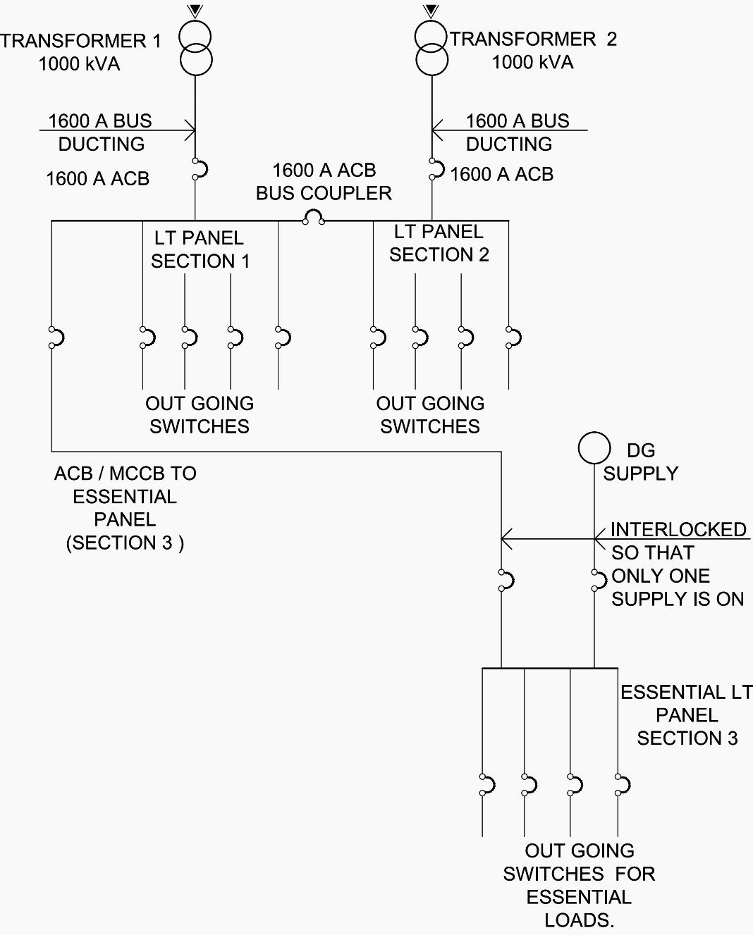
In order to meet the power demands of essential UPS loads that require a high-quality input without any harmonics or surges, it is necessary to install an appropriate isolating transformer after the UPS.
Figure 1 – Schematic diagram for a substation with two transformers, one DG set, and one essential panel connecting essential loads
1.2 Dry or Oil-Cooled Transformer?
It is prohibited to place oil cooled transformers indoors. They are permitted when the substation is located at a distance from the main building. It is advisable to choose a dry transformer instead of an oil-cooled transformer for the following reasons:
- Highly resistant to fire and explosion.
- Virtually maintenance-free.
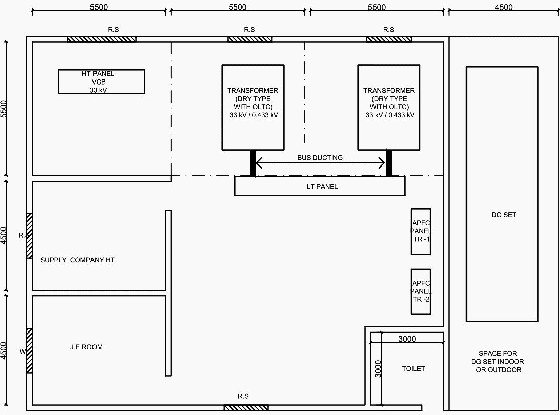
- There is no need for a wall enclosure for the transformer, therefore the space needed for the substation is decreased. The substation layout can consist of a single hall (Figure 2) with VCB Medium Voltage Panel and dry transformers.
Figure 2 – Typical layout for 33/0.433 kV substation with 33kV incomer and two 2000kVA 33/0.433kV transformers
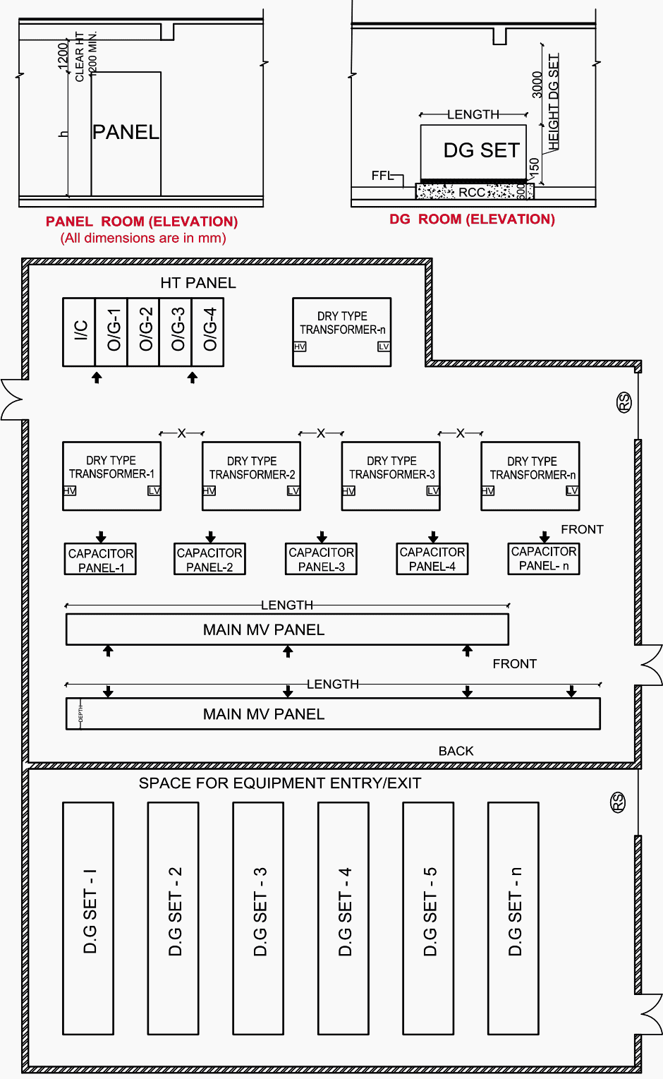
Please refer to the enclosed room type substation layout, which has dry transformers and does not have any room enclosures. This occupies a significantly smaller amount of space. See Figure 3.
Figure 3 – Typical substation layout with dry-type equipment in a single room
1.3 OLTC Transformers and Voltage Stabilization
Varying voltage poses a significant risk to the equipment. It is customary to shut down the equipment if the supply voltage falls below 380 volts or exceeds 440 volts. Consequently, it is advisable to include a transformer with an on-load tap changer (OLTC) as a customary measure to ensure the protection of the equipment.
If the voltage level from the supply company has a big variance and there is no On-Load Tap Changer (OLTC), then it is necessary to install several voltage stabilizers throughout the building!
Good Reading – 11 factors that significantly influence the transformer price (Be careful when specifying)
11 factors that significantly influence the transformer price (Be careful when specifying)
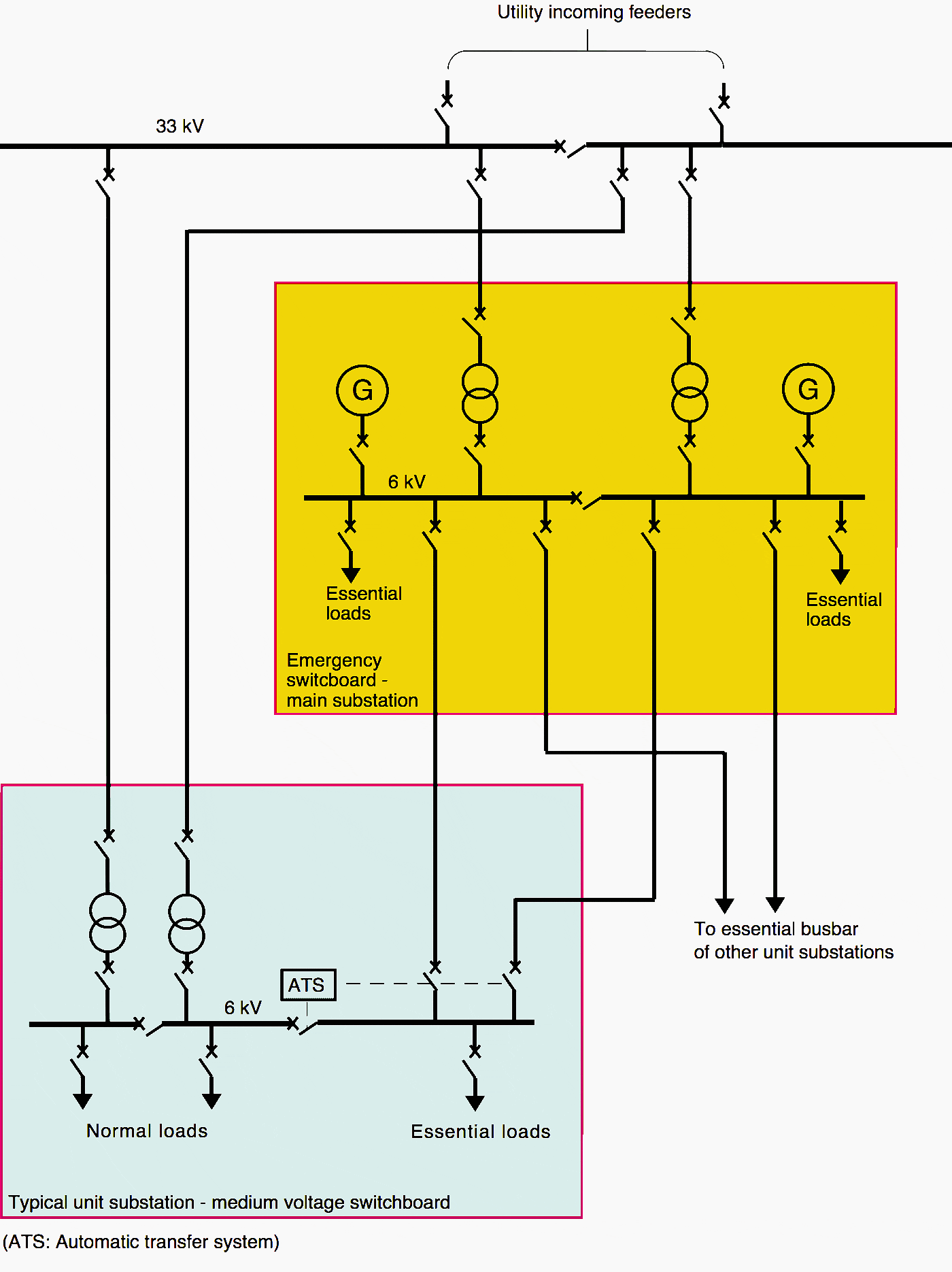
1.4 Distribution Substations With DG Backup
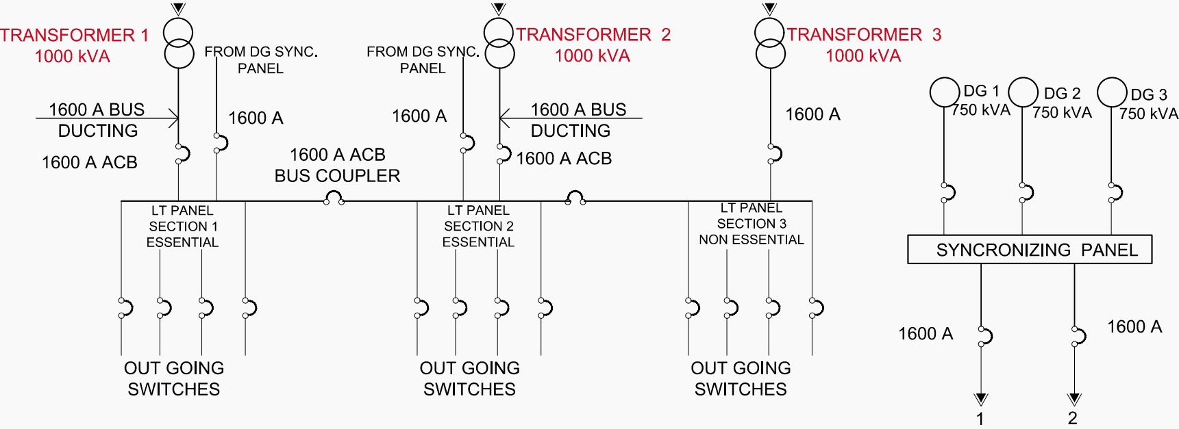
It is advised that each distribution substation should have its own DG Backup so that in case of mains power loss local DG sets are available as backup as per the standard procedure. Having a centralized DG Backup to provide 11 KV DG Power to the distribution substations is not advisable.
This will prevent the segregation of essential and non-essential resources. In the event of any malfunction in the 11 KV feeder cable, the entire campus will be without DG Backup.
Figure 4 – Schematic diagram of a substation with three transformers 1000kVA feeding two sections of essential LV panel and one section of non-essential LV panel with three 750kVA DG sets through synchronizing panels (click to zoom)
1.5 Indoor or Outdoor DG Sets
Typically, indoor DG units are permitted for installation within buildings. Nevertheless, the decision to place them within or outdoors is determined by the technical sanctioning authority, who carefully considers all relevant factors. Indoor DG sets can be installed if there is an appropriate system for removing smoke and providing the necessary amount of fresh air.
Frequently, the conditions at the site do not allow for the installation of DG Sets in an outdoor location. Installing DG units indoors has become a prevalent practice due to architectural, aesthetic, and security considerations, as well as the limited availability of outdoor area.
Figure 5 – Generator set (genset or DG set) placed indoors

1.6 Installation of SCADA Panel in Substation
In order to digitally monitor and log the parameters of the substation, it is recommended to install a SCADA Panel, provided that the increased cost is justified by its usefulness.
Figure 6 – SCADA screens and panels behind

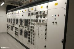
1.7 Installation of Main Low-Voltage Panel
Conforming to IEC 61439 and other relevant International Standards
All main low-voltage panels MUST conform to IEC 61439 and other relevant International Standards for ensuring proper quality. The manufacturer must have a valid type test certificate for the current rating of the busbar that is equal to or greater than the indicated current rating.
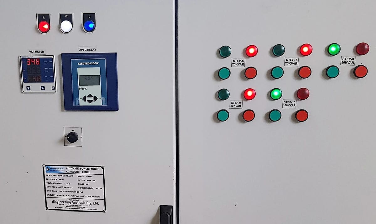
1.8 Automatic Power Factor Correction (APFC) Panel
Installation of Automatic Power Factor Correction (APFC) Panels is necessary to ensure a power factor (PF) of 0.99. This is because improving the PF from 0.8 to 1.0 results in a 20% reduction in load current.
Figure 7 – Automatic Power Factor Correction (APFC) Panel
1.9 Centralized AC Plant, Substation and UPS
The primary benefit of centralization is the utilization of the diversity factor, backup capabilities, reduced maintenance requirements, and the advantage of economies of scale. For instance, implementing district cooling for the entire campus through a single central plant is more cost-effective than installing multiple plants across the campus or using a large number of individual AC units.
The same principle applies to UPS systems.
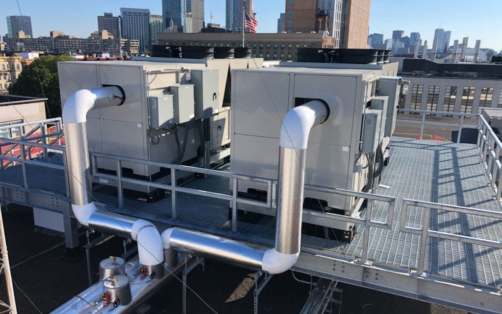
1.10 Larger-Capacity Equipment
It is recommended to use larger-capacity equipment such as transformers and chillers in order to minimize the amount of equipment needed and the overall space required in the utility building. This decision should be based on factors such as efficiency, life cycle cost analysis, and consideration of no load losses.
Figure 8 – Rooftop chillers installations
1.11 Future Substation Expansion and Additional Space
Each substation should be equipped with the capability to accommodate the installation of at least one additional transformer and the expansion of the low voltage panel in order to accommodate future increases in power demand.
Good Reading – Design guide to digital control and communication systems in modern substations
Design guide to digital control and communication systems in modern substations
1.12 Protection against overload, short-circuit, earth leakage and surge
The flow of power from the transformer to individual loads occurs in the following sequence:
- Medium Voltage (MV) Panel to transformer. MV panel with overload/ short-circuit/earth leakage protection of transformer.
- Transformer to Low Voltage (LV) panel through ACB.
- LV Panel to building main switch through outgoing ACB/MCCB.
- Power is received in building main LV Panel with incoming ACB/MCCB and outgoing MCCB.
- Outgoing MCCB to feed rising main with incoming MCCB.
- Tap-off from rising main at each floor feeds the floor panel with incoming MCCB and outgoing MCCB.
- Outgoing MCCB of floor panel feeds DB with incoming MCCB/MCB and outgoing MCCB/MCB.
- Outgoing from DB feeds the load on light/power circuit.
- Power load at the end of the power circuit is through by MCCB/MCB.
- Therefore the power flows from the transformer to the load through a number of ACBs/MCCBs/MCBs with overload/short-circuit /Earth leakage /Surge protection through properly designed switchboards.
Consequently, it is possible to have up to 12 pieces of ACB/MCCB/MCB connected in a series, each equipped with overload, short circuit, and earth leakage protection, prior to the power being supplied to the load. A well-designed electric installation includes comprehensive safeguards against overload, short-circuit, earth leakage, and surge.
An electrical fire occurs due to either an overload or a short circuit, while electrocution happens as a result of earthing failure. An appropriately engineered and well-maintained electrical system will effectively eliminate the risk of electrical fires and electric shock. Therefore, it is imperative to prioritize these factors during the process of planning and implementation.
Further Study – Fundamental concepts of schematic drawings for true field engineers (hands on HV schemes)
Fundamental concepts of schematic drawings for true field engineers (hands on HV schemes)
1.13 Fuseless Protection System
Typically, only ACBs/ MCCBs/ MCBs should be utilized in most applications as they are all fuseless and resettable. It is not advisable to employ slow-acting rewirable fuses due to their potential to cause fires. HRC fuses are known for their quick response time. However, they are sometimes substituted with rewirable fuses, which pose a risk of fire.
HRC fuse switches have a larger physical footprint in comparison to MCCBs. As a result, they are typically not employed in cubicle panels due to limitations in available space.
Further Study – Major components you can spot while looking at opened LV and MV switchboards
Major components you can spot while looking at opened LV and MV switchboards
2. Uninterrupted Power Supply
The goal of ensuring continuous power supply is accomplished by the following methods: Initially, evaluate the electricity demand of the building or campus. Ensuring adequate allocation for anticipated electricity expansion, which is conservatively estimated at an annual growth rate of approximately 5%.
As an illustration, the peak power consumption of Delhi, an Indian city, has risen from 4700 MW in 2010 to 7000 MW in 2018, representing a growth of 50% over a span of 8 years.
The campus’s full development, including the load growth, may take approximately 5 to 10 years. To accommodate this growth, it is advisable to have a flexible contract with the supply business, allowing for progressive expansion. Additionally, it is recommended to allocate space in the layout for future extension of the substation building to accommodate the increased load.
Figure 9 – Typical schematic diagram for a substation power distribution
2.1 Load Demand Assessment
During the first estimation process, the specific characteristics of the load are not yet clear. There can be significant discrepancies in the load estimate created by different designers. For instance, in the case of a single campus, one designer would compute the maximum demand to be 10 MVA, while another designer might estimate it to be 15 MVA.
An effective approach is to obtain the real-time energy consumption of comparable operational buildings, measured in watts per square meter (W/m2). To calculate electrical loading, excluding air-conditioning, for significant buildings, it is reasonable to assume a power requirement of 40 watt/m2 for high load intensity buildings and 25-30 watt/m2 for medium load intensity buildings, based on the actual power demand of these buildings.
Contemporary structures are equipped with centralized air conditioning systems to optimize productivity, enhance human comfort, and improve indoor air quality. Approximately half of the energy consumption is allocated to air conditioning. Hence, in order to achieve optimal air-conditioning, it is advisable to use suitable architectural measures such as envelope insulation to minimize the building’s heat load.
It is recommended to implement a solar power backup system in addition to the existing arrangement in order to decrease the Substation KVA and cut electricity expenses.
When calculating the load, if the initial value is 10 MVA using conventional technology, it is possible to decrease this load to 7 MVA by implementing energy-efficient lighting, fans, appliances, energy-efficient AC with variable frequency drive (VFD), building management system (BMS), optimizing building orientation, and improving insulation. The reduction of 3 MVA results in a capital outlay savings of approximately 800,000 USD and an annual energy cost savings of 400,000 USD (assuming that 1 MVA requires an energy cost of around 1 crore per year).
With a solar backup capacity of around 1 to 2 MVA, the substation’s MVA is further decreased to 6MVA/5MVA.
Summary of load assessment:
- For electrical loads: 25 to 40 watt/m2 of built-up area.
- Medical equipment/laboratory equipment loads: add 25 %.
- Central AC Load: 40 watt/m2 of AC area subject to energy efficient AC. For inefficient AC like Window/Split AC/VRV add 20% extra.
- DG aggregate capacity: about 50-60 % of transformer capacity.
- UPS aggregate capacity: 20-25 % of transformer capacity.
- Solar generation: 5-10 % of transformer capacity but more can be provided if land for solar panels is available.
Good Reading – Load flow and short circuit analysis of a MV substation (case study 33/11 kV substation in ETAP)
Load flow and short circuit analysis of a MV substation (case study 33/11 kV substation in ETAP)
3. Active & Strategic Involvement of Planning Engineer
The Electrical Engineer must actively contribute to reducing the building’s load demand by employing suitable technology and collaborating with the architect to implement methods that minimize heat infiltration into the building.
The Energy Conservation Building Code (ECBC) offers guidance for energy conservation by recommending the use of energy-efficient equipment and implementing architectural measures such as building orientation and envelope insulation. Therefore, it is necessary to adhere to the ECBC guidelines.
4. Where to Locate Distribution Substations?
The placement of the receiving substation will be determined through collaboration between the supply provider and the architect. Typically, it is located on the outside of the campus.
The next step is to identify the different distribution substations. In order to minimize the expense associated with voltage drop in cabling, it is recommended that each substation supplies electricity within a maximum distance of 200 meters. It is desirable for the substations to be separate structures located on the ground level, specifically designed to accommodate auxiliary services such as DG Sets and UPS.
Within a building equipped with central air conditioning, half of the electrical energy is utilized by the air conditioning system. Hence, locating the plant room in close proximity to the substation would result in a decreased expenditure on connectivity.
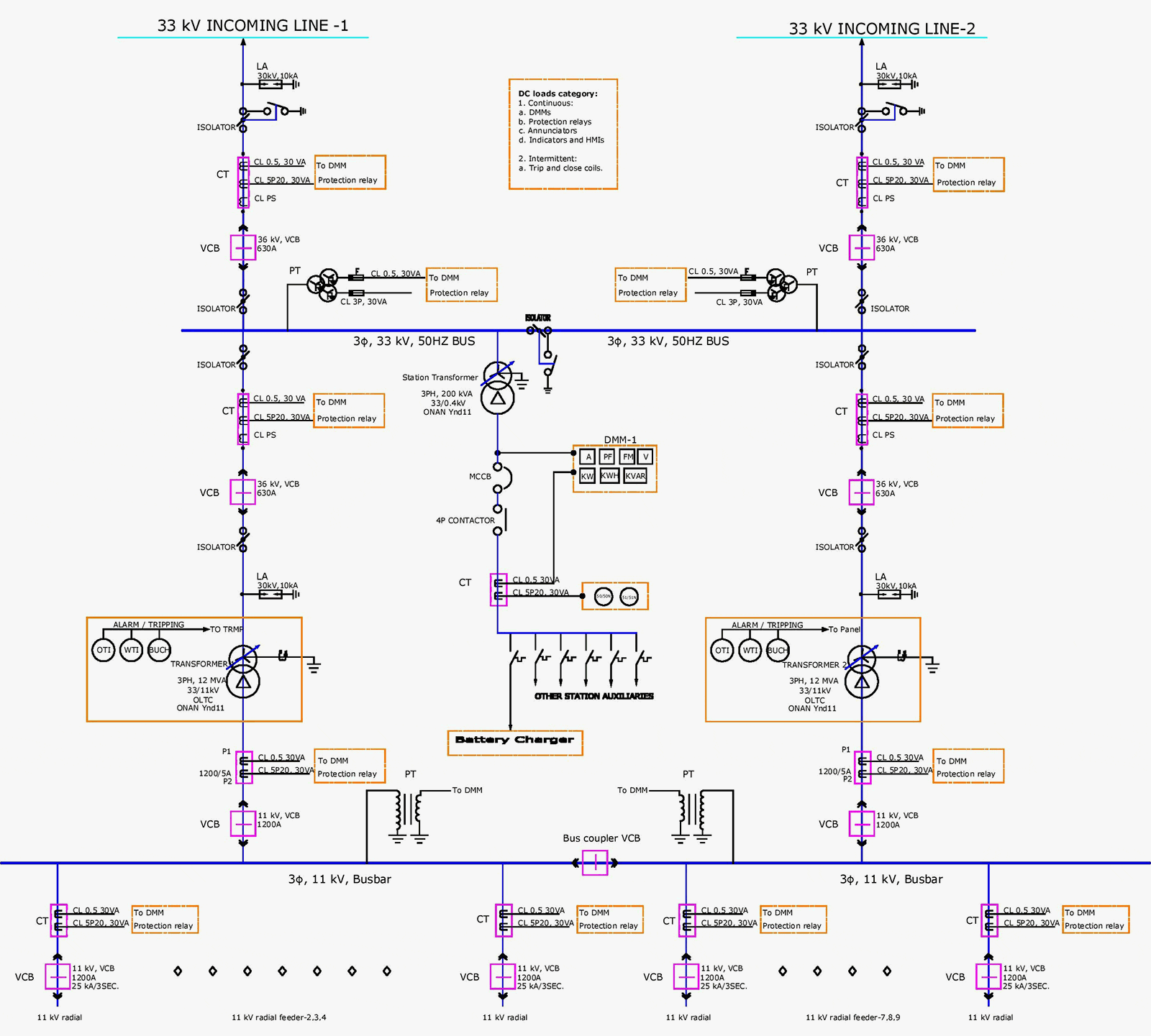
Figure 10 – Single line diagram of a 33/11 kV power distribution substation (click to expand the diagram)
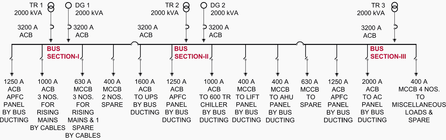
5. Standby Systems
It is probable that any equipment, including electrical devices, will have malfunctions. Hence, in order to ensure continuous supply, it is imperative to have backup systems in place. To ensure redundancy, two 1000 kVA transformers should be placed at the substation, each capable of handling the whole load. This arrangement allows for seamless operation in the event of a breakdown in one of the transformers.
Additionally, a backup DG set is installed to ensure that in the event of a power breakdown from the primary source, the DG set will immediately activate and power the important loads. If there is a disruption in the main power supply, it may take around 30 seconds for the DG set to initiate. To ensure uninterrupted power supply to UPS loads, a UPS system is given for the specified period of time.
The DG Sets and UPS system are equipped with standby units to ensure an uninterrupted power supply system, in conjunction with the mains supply.
A standard campus typically has a single 33KV receiving substation, equipped with one or two incoming 33 KV feeder lines. This substation is connected to a 33 KV MV panel, which supplies power to 33KV/11 KV or 33 KV/0.433 KV transformers based on special needs. It has the capacity to supply electricity to about 4 or more distribution substations located throughout the campus.
A typical layout of 33 KV substation and various alternate power distribution schematic diagrams are depicted in Figures 11 and 12.
Figure 11 – Schematic diagram for 33kV receiving substation feeding number of 11/0.433 kV distribution substations through 11kV cabling
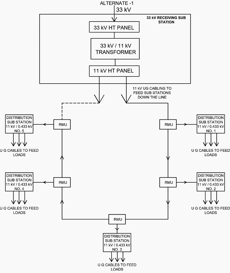
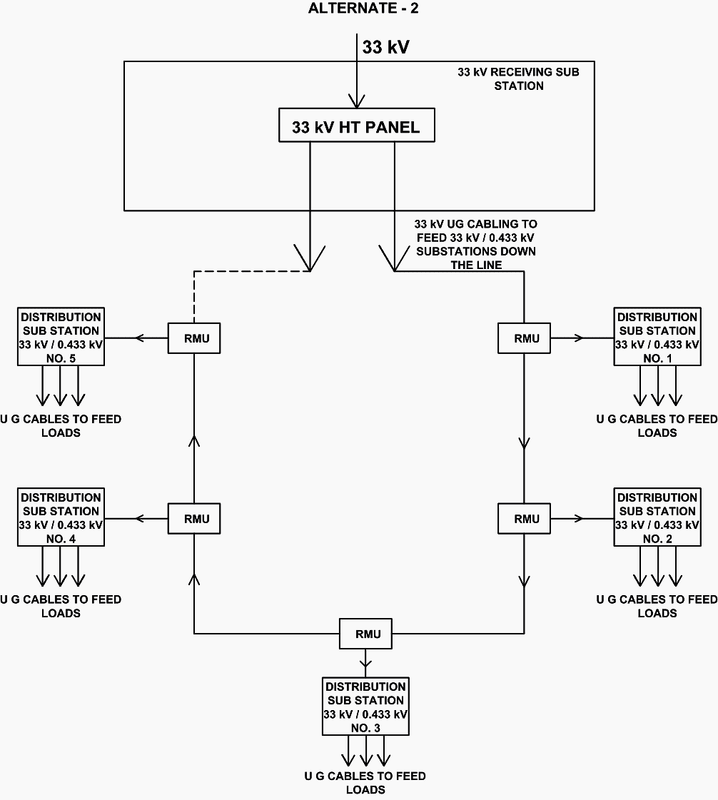
Figure 12 – Schematic diagram for 33kV receiving substation feeding number of 33/0.433 kV distribution substations through 33kV cabling
Typical layout of an 11KV/0.433 KV or 33KV/0.433 KV distribution substation is detailed in Substation specifications.
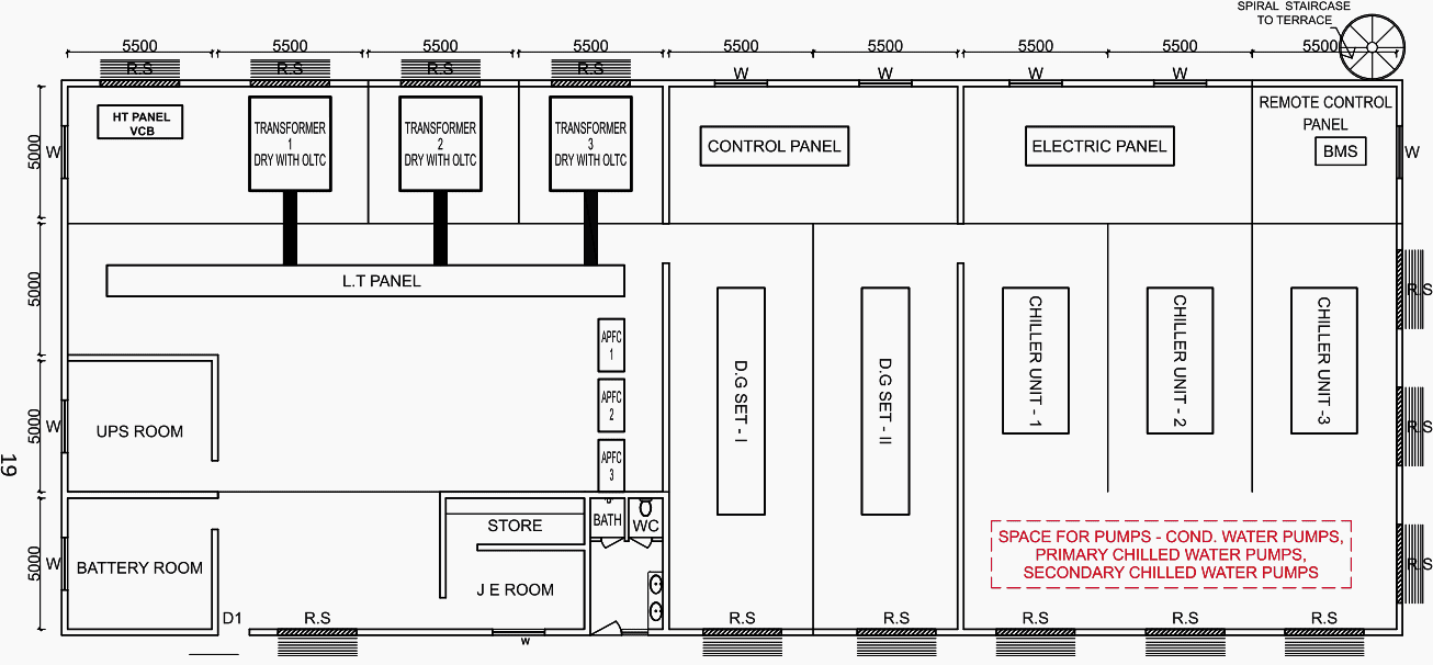
A common diagram illustrating the components of a substation, including the MV Panel, Transformers, Bus ducting, LV Panel (Essential and non-essential), APFC Panel, DG Sets, DG Synchronizing Panel, UPS, and Battery Room, is provided for general reference (Figure 13). These may be subject to change depending on specific requirements.
Figure 13 – Typical layout of DG sets, substation equipment, AV plant room and UPS (click to zoom)
Notes:
- Floor to ceiling height 6.5 m, floor level 30 cm above ground level.
- Motorable concrete approach road all round.
- Partition walls – 30 cm thick brick
- Spiral staircase to terrace for terrace maintenance and approach to equipment on terrace.
- 1 m wide sun shade protection all around.
- Rolling shutter – 3 m wide – 3.5 m height. With ventilation grids.
- All doors of steel with fire protection , d1 – 1 m wide 2 m height.
- W – window – normal size with grill.
- Cable entry pipes — ex. Engineer will give location and details.
- Cable trenches – ex. Engineer will give details.
- Protection boundary wall with gate – if substation is protected premises, suitable boundary wall with gate should be provided.
- Store shelves – 0.75 m deep, rcc 1m , 2m ,3m above ground level.
- 2000 ltrs. Water tank on the terrace with water connection.
- Cooling towers will be located on the terrace.
- Locate exhaust chimney and UG bulk storage tank
6. Power Supply in Individual Buildings
The Main Low-Voltage Room is designed to receive electrical power from the substation. The system will have essential, non-essential, and UPS main panels for the reception and distribution of power. All the electricity supply for the building will be monitored and controlled from the primary low voltage (LV) room. If possible, the distribution of power should always go vertically through rising mains, which are far more advanced compared to rising cable systems.
Benefits of a rising main in comparison to a cable system:
- Occupies a significantly smaller amount of space.
- Significantly reduced risk of fire.
- In the future, it will be possible to harness extra power from the rising main without the need for further cable installation.
- Secure.
- Technologically advanced.
The next step is to determine the number of vertical shafts that will be used for the main pipeline. Each shaft will contain the following vertical pipes:
- The equipment rising main is a crucial component for hospitals and laboratories since it allows for the dedicated transmission of equipment through specific cables.
- UPS Rising main.
It’s advisable that the power is supplied at each level from the rising main through a tap off box located at the floor panel. The floor panel should be equipped with both incoming and outgoing switches to supply power to the loads. For supplying power to the rising mains from the LV Panel, it is more advantageous to utilize bus ducting rather than using multiple cables.
Figure 14 – Civil engineering in installation of substation buildings and switchboard rooms

7. Power Supply to Central AC Plant
In a centrally air-conditioned building, where AC consumes 50% of the electricity, it is advisable to position the AC Main Electrical Panel near the substation to minimize connections expenses. The AC Electrical Panel will be divided into two distinct sections: Essential and Non-Essential.
Certain chillers, along with the pumps and cooling towers, will be designated as essential supply. It is necessary for all Air Handling Units (AHUs) to be connected to the DG Supply. Consequently, there will be two primary power sources connected to the main AC Panel, which will be linked to the Substation LT Panel via Bus ducting.
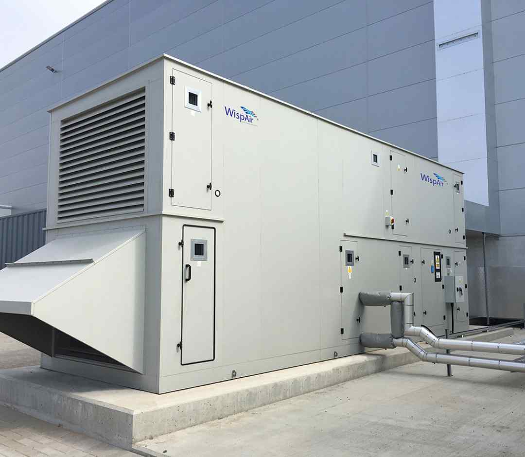
A primary Electrical panel will be installed to provide power to the Air Handling Units (AHUs).
Figure 15 – Air Handling Unit (AHU)
8. Power Supply to Air-Handling Units (AHUs)
The Air-Handling Units (AHUs) CAN be arranged in a vertical configuration, with each unit positioned directly over the other. Then, the rising main can be installed to supply power to the Air Handling Units (AHUs). The incoming of each ascending primary conduit should be linked to the outgoing of the Air Handling Unit (AHU) Main Panel situated in the Air Conditioning (AC) Plant Room.
This greatly simplifies the power supply to the Air Handling Units (AHUs).
Furthermore, the process of connecting the system to the Building Management System (BMS) is highly straightforward.
Suggested Video – Air Handling Unit Working principle
9. Integrated Building Management System (IBMS)
If a modern building complex is present, an Integrated Building Management System (IBMS) can be installed. The power distribution system can be configured to be compatible with IBMS, allowing for centralized monitoring and control of the entire system.
10. Planning of Building Services
An experienced electrical design engineer should be engaged during the initial planning phase to ensure the installation is sufficient for its intended purpose and guarantees safety, dependability, and energy efficiency in its operation.
Good Reading – Five substation building services that usually lack of proper design (and make troubles later)
Five substation building services that usually lack of proper design (and make troubles later)
10.1 Location of Substations and Switch Rooms
It is advisable to place the substation in a distinct utility building, and it might be positioned next to the generator room, if one exists. Avoid locating the substation in the basement whenever feasible. If a building has only one basement, the substation/switch room should not be located in the basement.
Furthermore, the substation’s floor level must not be situated at the lowest point of the basement.
When it comes to oil-filled installations, substations that have equipment loaded with oil need to carefully consider fire detection, protection, and suppression measures. Substations containing oil-filled equipment, like as transformers and medium voltage panels, must be situated either in an open area or within a dedicated utility structure.
They must be situated exclusively on the ground level or the first basement of a utility building. They will be granted unobstructed entry from the exterior of the structure for the purpose of operating and maintaining the equipment.
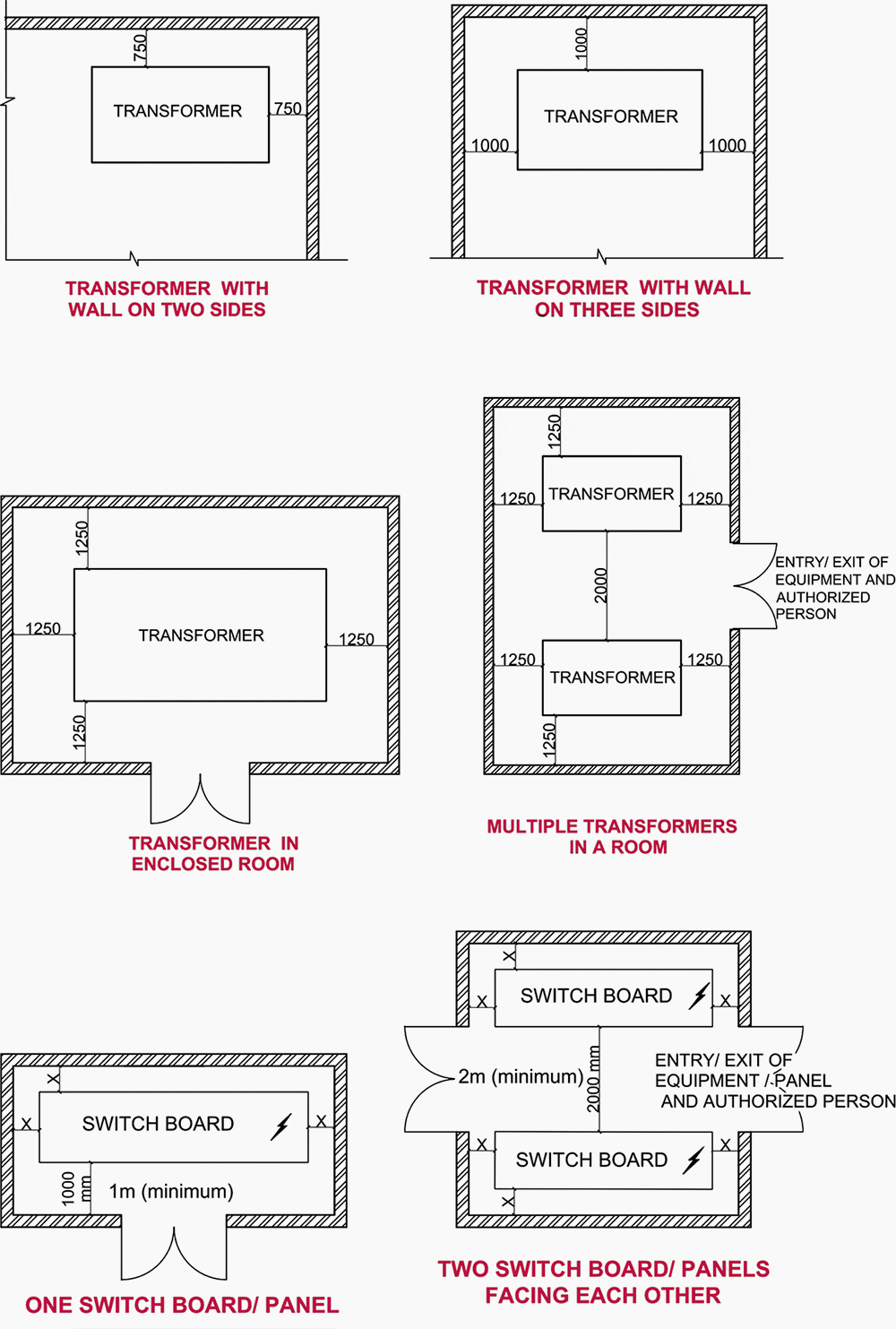
If there are two transformers (either dry type or transformers with oil quantity less than 2000 litres) placed adjacent to each other without a wall in between, the minimum distance between them should be 1500 mm for 11 kV, 2000 mm for 22 kV, and 2500 mm for 33 kV. For voltages over 33 kV, it is required to provide a baffle wall with a fire rating of 4 hours between two transformers.
The minimum height of the substation/MV switch room/MV switch room should be determined by taking into account the need for a 1200 mm clearance from the top of the equipment to the underside of the beam’s soffit.
Figure 16 – Dry-type cast resin transformer

10.2 Emergency Power Backup System
Installation of emergency power supply, such as generating sets, is prohibited on any floor above the ground floor or below the first basement level of the building. If a DG set is situated in the basement, the ceiling of the basement will serve as the ground floor slab. The optimal location for installing the standby generator is within the utility building.
When the equipment is situated in a confined area, it is necessary to have a system for forced ventilation in place to ensure that the equipment’s performance is not significantly reduced.
The acoustic enclosure for DG sets or the acoustic lining for the DG room must comply with the specifications outlined in the National Code. If a DG set is situated outdoors, it is imperative that it be placed within an acoustical enclosure or treated with soundproofing measures.
Figure 17 – Typical regular and emergency power supply system
10.3 Distribution Panels Location and Requirements
It is necessary to install distribution panels and switchgear in easily accessible locations. The electrical control gear distribution panels and other necessary apparatus should be conveniently placed next to the rising mains on each floor. Sufficient space must be allocated on each floor to ensure proper clearances for this purpose.
Figure 18 – Substation transformer and switchboard clearances
11. Distribution of Power Supply and Cabling
Modern building technology requires power distribution systems and their constituent components to meet rigorous standards and specifications.
- Durability and high-quality performance,
- Fire safety measures,
- Minimal combustible materials present,
- While there is flexibility in choosing the position and connection of the load, it is crucial to be meticulous in the design process,
- Minimal space requirement, and
- Minimal exertion required to perform retrofits.
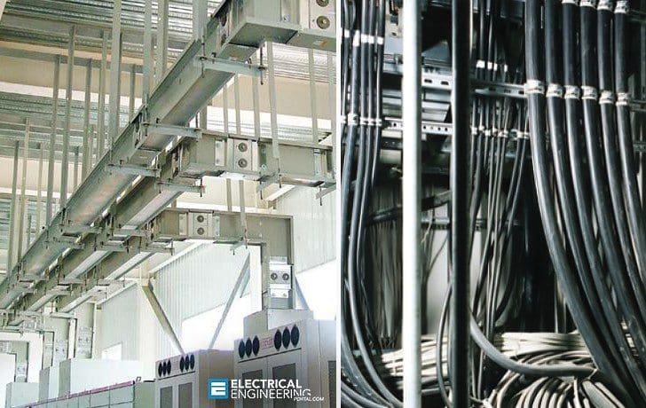
Modern huge structures and high rise buildings require a compact and secure solution for power supply due to their high load density. The utilization of bus bar trunking technology is optimal for such applications.
The selection of bus bar trunking for distribution in buildings can be determined based on:
- Significantly decreased fire load (in stark contrast to the cable/system)
- Decreased upkeep during its whole lifespan
- Extended durability compared to cable distribution
- The reliability is improved by using strong bolted joints and terminations, which greatly reduce the chances of insulation failure.
Figure 19 – Left: Horizonal and vertical bus bar trunking; Right: Cable Trunking System
11.1 Distribution Transformers
An important design purpose when selecting transformers for a substation is to ensure the inclusion of at least two or more transformers, in order to incorporate a level of redundancy. The entire installed capacity must exceed the estimated maximum demand by a minimum of 15 to 20%.
The system design is optimized to accommodate both high and low levels of loading, in response to the increasing focus on energy conservation. It is preferable to operate only one transformer during times of minimal load in the system, and then activate the other transformer as the load gradually grows during the day.
The total capacity of transformers is often determined based on the current load and potential future load.
In the event that many transformers are to be put in a substation to provide power to a medium voltage distribution system, it is necessary to divide the distribution system into distinct sections. Each section should typically receive power from a single transformer. In the case of a transformer failure or disconnection, it is possible to establish a connection between different sections by using a bus coupler.
Further Study – Learn how to prepare for transformer acceptance tests and final inspections
Learn how to prepare for transformer acceptance tests and final inspections
BONUS: Download handbook ‘Electric Distribution Systems’ in PDF format
Download BONUS: Download handbook ‘Electric Distribution Systems’ (576 pages, PDF) (for premium members only):
Related electrical guides & articles


Edvard Csanyi
Hi, I'm an electrical engineer, programmer and founder of EEP - Electrical Engineering Portal. I worked twelve years at Schneider Electric in the position of technical support for low- and medium-voltage projects and the design of busbar trunking systems.I'm highly specialized in the design of LV/MV switchgear and low-voltage, high-power busbar trunking (<6300A) in substations, commercial buildings and industry facilities. I'm also a professional in AutoCAD programming.
Profile: Edvard Csanyi
