
Estimated Study Time: 14 minutes
Transformer protection relaying
This technical article provides three examples of the application of modern relays to transformer protection. As there are many modern protection relays nowadays that provide advanced software to simplify the calculations, in this article we will use earlier Alstom type KBCH relay to show the complexity of the required calculations.
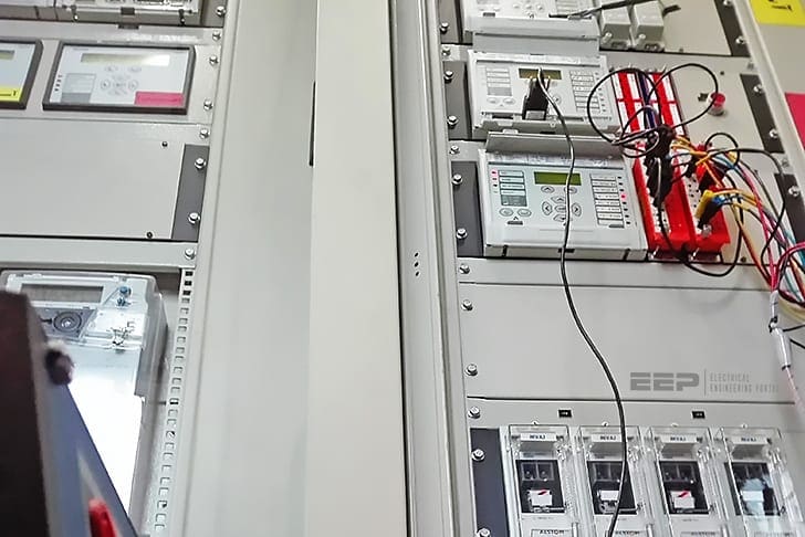 Three good examples of the application of modern relays to transformer protection (photo credit: Morteza Ravangard via Linkedin)
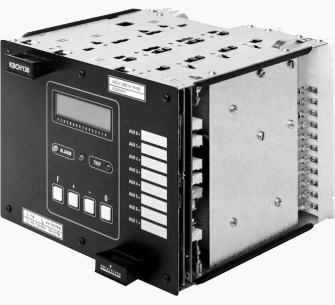
First. let’s say a word about KBCH relay we will use for calculations.
KBCH relay offers biased differential current, restricted earth fault (REF) and overfluxing protections primarily for the protection of two or three winding power transformers, auto transformers or generator-transformer units. The KBCH is also suitable for other applications where biased differential protection is appropriate (eg. generators, reactors and motors).
All models are three phase units with internal vector group compensation and line current transformer ratio correction, thus eliminating the need for interposing transformers in most cases.
Biased differential element
Each relay, contains a biased differential element per phase with a characteristic as shown in Figure 2. The minimum differential current required for operation is adjustable between 10% and 50% of rated current.
The KBCH has a dual slope bias characteristic (Figure 2). The initial slope of 20%, from zero to rated current, ensures sensitivity to faults whilst allowing for up to 15% mismatch when the power transformer is at the limit of its tap range, in addition to current transformer ratio errors.
At currents above rated, extra errors may be gradually introduced as a result of CT saturation. The bias slope is therefore increased to 80% to compensate for this.
- Provision of vector group compensation and zero-sequence filtering
- Unit protection of a delta-star transformer
- Unit protection for On-Load Tap Changing (OLTC) Transformer
1. Provision of Vector Group Compensation and Zero-Sequence Filtering
Figure 1 shows a delta-star transformer to be protected using a unit protection scheme. With a main winding connection of Dyn11, suitable choices of primary and secondary CT winding arrangements, and software phase compensation are to be made.
With the KBCH relay, phase compensation is selected by the user in the form of software-implemented interposing current transformers (ICTs).
With the Dyn11 connection, the secondary voltages and currents are displaced by +30° from the primary. Therefore, the combination of primary, secondary and phase correction must provide a phase shift of –30° of the secondary quantities relative to the primary.
For simplicity, the CTs on the primary and secondary windings of the transformer are connected in star. The required phase shift can be achieved either by use of ICT connections on the primary side having a phase shift of +30° or on the secondary side having a phase shift of –30°.
However, the distribution of current in the primary and secondary windings of the transformer due to an external earth fault on the secondary side of the transformer must now be considered.
The transformer has an earth connection on the secondary winding, so it can deliver zero sequence current to the fault.
Use of star connected main CTs and Yy0 connected ICTs provides a path for the zero sequence current to reach the protection relay. On the primary side of the transformer, the delta connected main primary winding causes zero-sequence current to circulate round the delta and hence will not be seen by the primary side main CTs.
The protection relay will therefore not see any zero-sequence current on the primary side, and hence detects the secondary side zero sequence current incorrectly as an in-zone fault.
The solution is to provide the ICTs on the secondary side of the transformer with a delta winding, so that the zero-sequence current circulates round the delta and is not seen by the relay.
Selection of Yy0 connection for the primary side ICTs and Yd1 (–30°) for the secondary side ICTs provides the required phase shift and the zero-sequence trap on the secondary side.
Modern numerical MiCOM relays employ a setting wizard, needing only vector group and zero sequence data to be entered. The relay then automatically adapts itself to suit the application.
2. Unit Protection of a Delta-Star Transformer
Figure 2 shows a delta-star transformer to which unit protection is to be applied, including restricted earth fault protection to the star winding.
Referring to the figure, the interposing current transformers (ICTs) have already been correctly selected, and are conveniently applied in software.
It therefore remains to calculate suitable ratio compensation (it is assumed that the transformer has no taps), transformer differential protection settings and restricted earth fault settings.
2.1 Ratio compensation
- Transformer HV full load current on secondary of main CTs is: 175 / 250 = 0.7
- Ratio compensation = 1 / 0.7 = 1.428
- Select nearest value = 1.43
- LV secondary current = 525 / 600 = 0.875
- Ratio compensation = 1 / 0.875 = 1.14
2.2 Transformer unit protection settings
A current setting of 20% of the rated relay current is recommended. This equates to 35A primary current. The KBCH relay has a dual slope bias characteristic with fixed bias slope settings of 20% up to rated current and 80% above that level.
The corresponding characteristic is shown in Figure 3 below.
2.3 Restricted earth fault protection
The KBCH relay implements high-impedance Restricted Earth Fault (REF) protection. Operation is required for a primary earth fault current of 25% rated earth fault current (i.e. 250A).
The requirements can be expressed as:
VS = Is Rstab
and
VS > KIf (Rct + 2Rt)
where:
- VS = stability voltage setting
- VK = CT knee point voltage
- K = relay stability factor
- Is = relay current setting
- Rct = CT winding resistance
- R1 = CT lead resistance
- Rstab = Stabilising resistor
For this example:
- VK = 97 V
- Rct = 3.7 Ω
- R1 = 0.057 Ω
For the relay used, the various factors are related by the graph of Figure 4.
Starting with the desired operating time, the Vk / Vs ratio and K factor can be found. An operating of 40ms (2 cycles at 50Hz) is usually acceptable, and hence, from Figure 4:
VK / VS = 4 and K = 0.5
The maximum earth fault current is limited by the earthing resistor to 1000A (primary). The maximum phase fault current can be estimated by assuming the source impedance to be zero, so it is limited only by transformer impedance to 5250A, or 10A secondary after taking account of the ratio compensation.
Hence the stability voltage can be calculated as:
- VS = 0.5 × 10 (3.7 + 2×0.057) = 19.07 V
- Hence, calculated VK = 4 × 19.07 = 76.28 V
- However, actual VK = 91 V and VK/VS = 4.77
Thus from Figure 4, with K = 0.5, the protection is unstable. By adopting an iterative procedure for values of VK/VS and K, a final acceptable result of VK/VS = 4,55 and K=0.6 is obtained. This results in an operating time faster than 40ms.
The required earth fault setting current Iop is 250A. The chosen E/F CT has an exciting current Ie of 1%, and hence using the equation:
Iop = CTratio x (IS + nIe)
where:
- n = number of CTs in parallel (=4)
- IS = 0.377, use 0.38 nearest settable value.
The peak voltage is estimated using the formula:
VP = 2 √(2VK(Vf – VK))
where:
Vf = if (RCT + 2Rt + Rstab)
and
If = fault current in secondary of CT circuit and substituting values, VP = 544V. Thus a Metrosil is not required.
3. Unit Protection for On-Load Tap Changing Transformer
The previous example deals with a transformer having no taps. In practice, most transformers have a range of taps to cater for different loading conditions.
For this example, the same transformer as in Section 2 will be used, but with an on-load tapping range of +5% to -15%.
The tap-changer is located on the primary winding, while the tap-step usually does not matter.
3.1 Ratio correction
The mid-tap position is used to calculate the ratio correction factors. The mid tap position is –5%, and at this tap position:
- Primary voltage to give rated secondary voltage = 33 x 0.95 = 31.35kV and Rated Primary Current = 184A
- Transformer HV full load current on secondary of main CTs is: 184/250 = 0.737
- Ratio compensation = 1/0.737 = 1.36
- LV secondary current = 525/600 = 0.875
- Ratio compensation = 1/0.875 = 1.14
Both of the above values can be set in the relay.
3.2 Bias slope setting
The on-load tapping range of +5% to -15% gives rise to a maximum excursion of -10% from the -5% mid-tap position.
As the differential scheme notionally balances at this mid-tap, this means that as an approximation, the maximum differential current that can flow when at top or bottom tap is 10% of the load (or fault current which may flow to an external fault).
Those relays having an adjustable k1 bias slope setting should ensure that it is at least 10% higher than the percentage excursion.
Source: Network automation and control guide by Alstom
Related electrical guides & articles


Edvard Csanyi
Hi, I'm an electrical engineer, programmer and founder of EEP - Electrical Engineering Portal. I worked twelve years at Schneider Electric in the position of technical support for low- and medium-voltage projects and the design of busbar trunking systems.I'm highly specialized in the design of LV/MV switchgear and low-voltage, high-power busbar trunking (<6300A) in substations, commercial buildings and industry facilities. I'm also a professional in AutoCAD programming.
Profile: Edvard Csanyi

very interesting topic and well defined also ,
Hi.
U used my pic at this topic & write : this pic credit by “Siboniso Mhlongo”!!!!!!!!!
Hi Morteza, sorry for this, it will be fixed ASAP!
How can a relay stabilized a system automatically at a higher frequency?
In underfrequency or overfrequency conditions, transformer become overexcited and therefore overheated and potentially damaged. You need Volts-per-Hertz (V/Hz) overexcitation relay which can operate at a too high voltage or at a too low frequency. Generally, the biggest chance for this to happen is in generator transformer units which can be overexcited during acceleration or deceleration of the turbine.