Many Options on the Table
Existing power systems are often modernized although there is no expansion involved at the moment. The switchgear may be obsolete, representing a real hazard to the operating personnel and property. The circuit breakers may also have an inadequate interrupting capacity. Substation equipment may be inadequate.
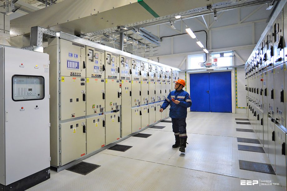
It’s quite possible that transformers may be old and have high losses and weak insulation, or cables may be old and their insulation brittle and subject to the increasing frequency of failure.
When modernizing the system by replacing switchgear, substations, or cable, be sure to see:
- If the plant distribution voltage should be increased, or
- If a different circuit arrangement should be used, or
- If more provision should be made for future expansion, or
- If the system should be made more reliable.
This technical article will try to shed some light on the way how to think of modernizing a power system in terms of dozen possible options while carrying the cost.
1. Replacing Old Switchgear
When modernizing or replacing existing obsolete switchgear, there may be cases where voltage is at the correct level and all other components of the system are adequate for the plant. In this case, the modern, safe, compact switchgear should be used instead of the old switchgear.
See Figure 1 below.
Figure 1 – Diagram showing how new metal-clad switchgear can be installed on a balcony above old switchgear to make the transfer of circuits from old to new switchgear easy and fast.
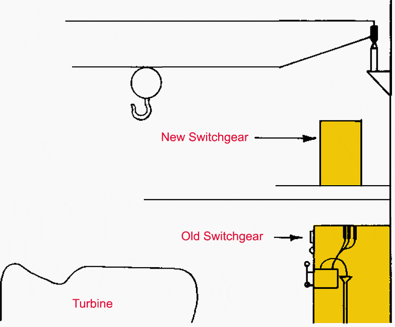

The new switchgear may be installed and then the feeder cables transferred from the old to the new switchgear one at a time. When replacing switchgear, be sure to check the system voltage and layout.
Perhaps you can get a completely new system for the price of a new switchboard, for example, a sawmill generated power at 600 V.
See Figure 2 below.
Figure 2 – Single-line diagram showing 600 V system as it existed in a lumber mill
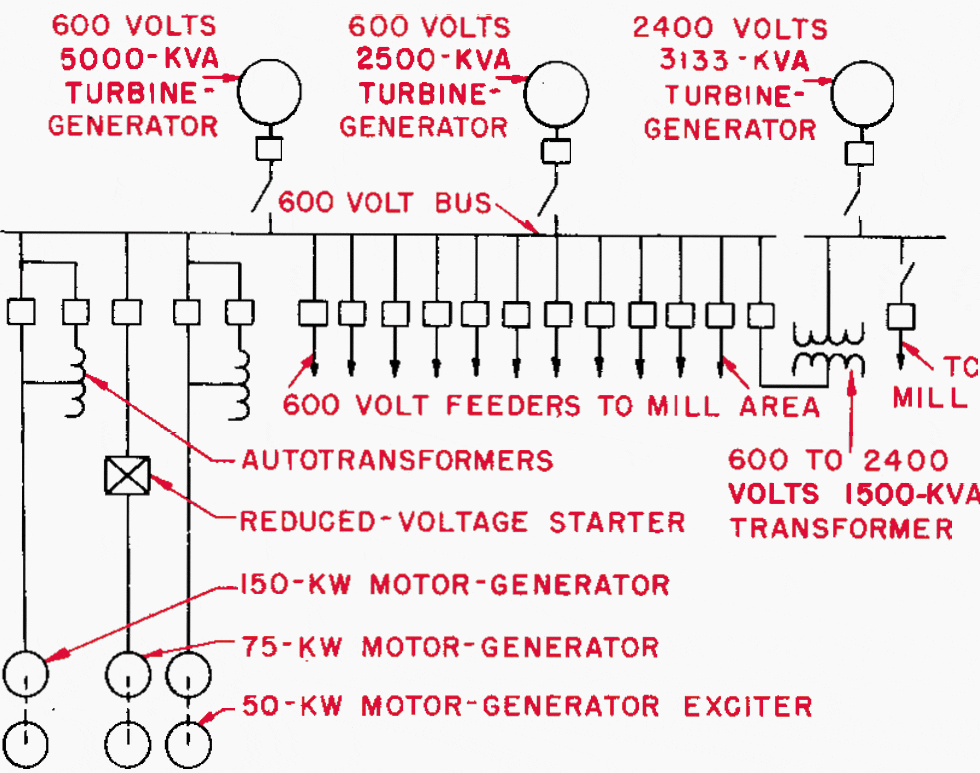

The plant engineers were aware of the inadequacy of the existing oil circuit breakers used on the 600 V system. One alternative was to install new 600 V switchgear, the cost of which was about $85,000.
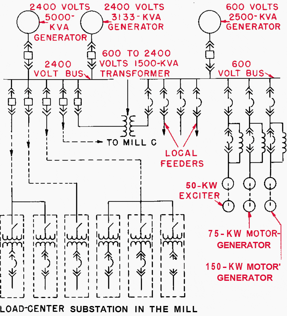
By rewinding one generator for 2400 V and adopting a load centre distribution system, a completely new power system (Figure 3), including new unit substations plus new windings in one generator, was obtained for approximately $20,000 more than the cost of a new 600 V switchboard.
The original system is shown in Figure 2 and modernized below in Figure 3.
Figure 3 – Single-line diagram showing the modernized system in a lumber mill

Go back to the Contents Table ↑
2. Replacing Old Substations
Many old power systems already have the most desirable primary and secondary voltages and may have relatively modern primary switchgear with digital protection. However, they may have old obsolete substations for stepping power down from primary voltage to utilization voltage.
When modernizing such substations, find out what system arrangement is best, and get more for the modernization dollar. For example, the following system existed in a metalworking factory in the East.
The voltage drop in the system was about 20% maximum, causing many operating difficulties with utilization equipment-such as a failure of fluorescent lamps to light. These substations could have been replaced at the same location with large unit substations of modern construction. Such large substations are costly and inflexible, however.
A review of this system showed two things:
- There were many big motors that could better be served at 2400 V instead of 480 V, and
- Small substations around the factory area would cost less than the larger substations.
They would improve voltage conditions and allow severa1 thousand feet of an existing secondary feeder cable to be sold as scrap. This would further increase the savings with the load-centre system. The system adopted (Figure 4) cost about 10% less than just replacing existing substations. The feeder voltage drop was decreased from 20% to about 2% maximum.
Figure 4 – Single-line diagram of modernized load-centre power distribution system where 480V load-centre unit substation and 2400V master unit substations replace old large low-voltage substations.
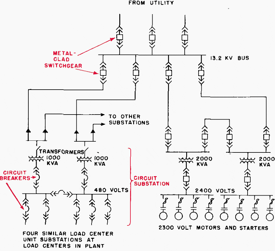

By adopting some substations with 2400 V secondaries, the larger motors (above 200 hp) which were purchased new were rated 2300 V instead of 440 V, as would have been necessary with the old system.
This change-over was made on a step-by-step basis, installing a few new load-centre unit substations each year. Thus, there was no large outlay of money during any one year for the modernization of the power system.
Go back to the Contents Table ↑
3. Replacing Old Cable
When cable insulation gets old, it usually gets brittle and mechanically weak. Cable failures have become so frequent in some old installations that something had to be done to correct the situation. One corrective approach might be to replace the existing old cable.
However, a better system might be obtained if a load-centre power system with higher voltage distribution were selected.
However, the cable copper losses were reduced in the load-centre system because the power is carried most of the way at high voltage instead of all the way at low voltage as with the old system.
Figure 5 – An old large low-voltage system (A) where all power was distributed over long low-voltage feeders
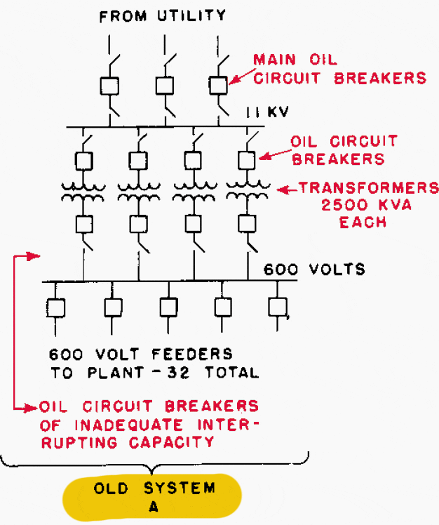

The capitalized savings in losses were $15,000 ($1500 annual saving in power bill capitalized at 10%). This reduced the cost of the load-centre system to only $175,000 ($190,000 – $15,000). The old 2500 kVA transformers had a resale value of $17,500. The net extra cost of the load-centre system was only $17,500 more than just replacing the cable.
The load-centre system had several advantages:
- Reduction in a feeder voltage drop (from 10% to 1.8%)-which improved performance of utilization equipment.
- New secondary distribution switchgear (600 V) of adequate interrupting capacity as obtained with the new load-centre power system.
- Lower cost future expansion of the system.
- More flexible system.
Figure 6 – A new load-centre system (B) for replacing an old large low-voltage system (A)
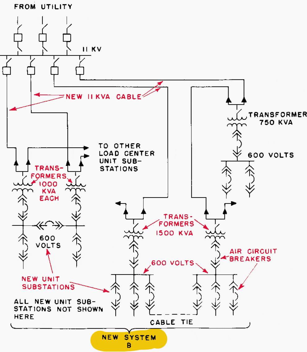

A completely modern system was obtained for only $17,.500, or $1.75 per kVA, by changing to the load-centre system instead of just replacing the cable. Again this change over-utilized the building-block characteristics of a load-centre system.
A few small substations have been added, and a few more will be added each year until the job is complete.
Go back to the Contents Table ↑
4. Expanding an Existing Plant
When expanding an existing plant, there is an ideal opportunity to start a modernization program of the power distribution system at little or no extra cost. Whenever an expansion is planned, check the system layout to see if a load-centre system would be better, but most, important-check to see if a higher distribution voltage would not be more economical.
This causes expansion of existing power systems. The most expensive single error often made is to design a power-system expansion on the basis that there will never be another expansion. Such a procedure makes it all the more expensive when the next expansion does come.
Suggested reading – Uprating and expanding existing power substations
Uprating and expanding existing power substations (good practice and recommendations)
The time to set up a proper power system is almost always at the time of the present expansion of an old system and not the next expansion. Here are several examples to illustrate the more important considerations when expanding a plant power system.
- Expanding a Small Plant
- Use Higher Voltage and Eliminate Double Transformations
- Expanding Plant Power Generating Systems
- Methods of Expanding at Higher Voltage
Go back to the Contents Table ↑
4.1 Expanding a Small Plant
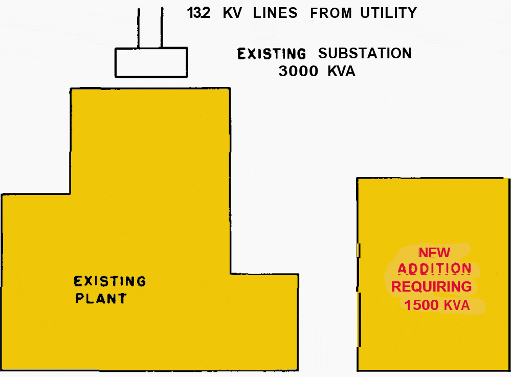
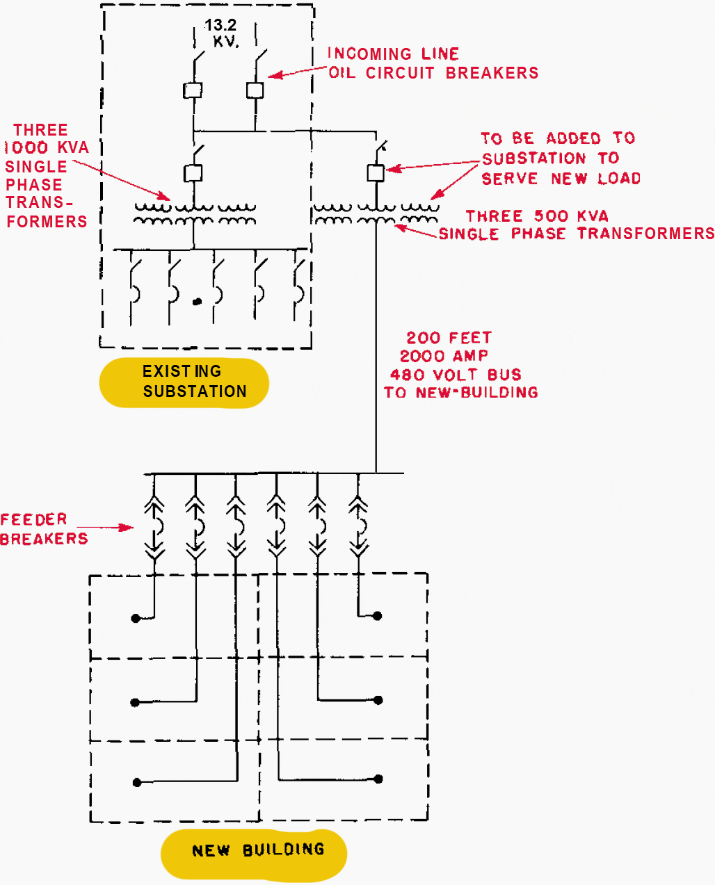
Supposing a plant (Figure 7) wants to add 1500 kVA of load in a new addition. The existing substation could be expanded as shown in Figure 8. This would cost about $26,000, the voltage drop would be 9%, and the cable copper losses would cost about $280 per year.
Making this expansion by a load-centre method (Figure 9), the high voltage would be taken to a load-centre unit substation at the load centre. The cost of the expansion by the load-centre method would be about $26,000. The voltage drop would be less than 1%, and feeder copper losses would be negligible.
Figure 7 – Layout of plant requiring 1500 kVA additional substation capacity

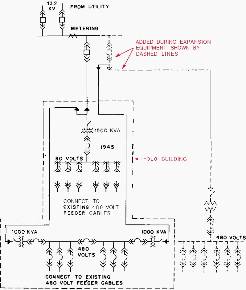
Therefore, by expanding this system on a load-centre system basis, the user saved $280 per year in losses at no increase in the first cost. Also, the user started a system that will fit into complete modernization of the plant (Figure 10) which can be done on a step-by-step basis and spread the expense over several years.
Figure 8 – Single-line diagram for expanding electrical system for plant shown in Figure 7 using low-voltage distribution to supply power in the new addition

For small or large plants, the same savings can be obtained by using the load-centre system for plant expansion. In larger plants, several small substations are used rather than a few large ones.
Figure 9 – Single-line diagram of expanded electrical system for plant shown in Figure 7 using load-centre distribution to supply power in the new addition
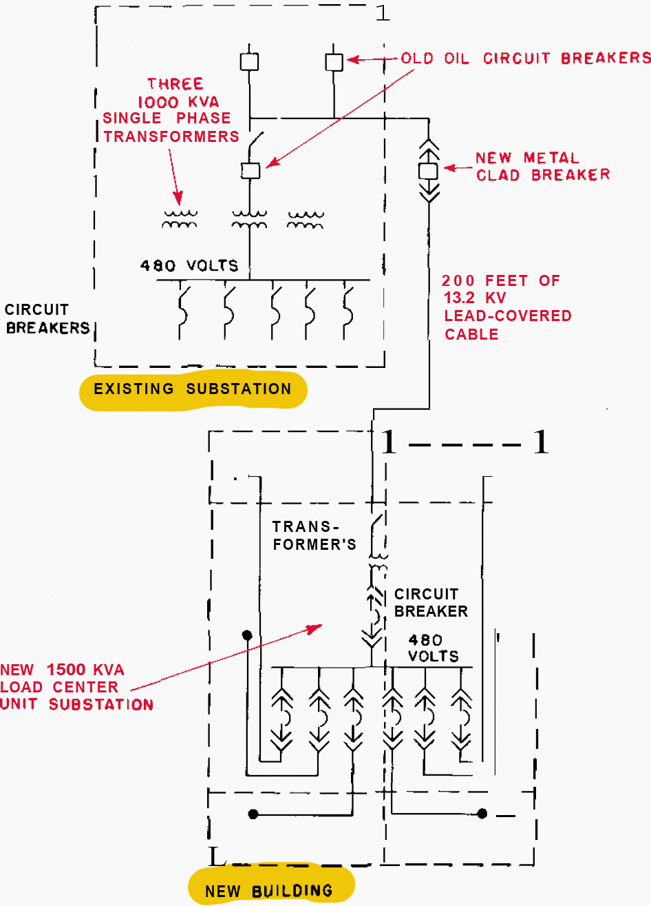

Figure 10 – Single-line diagram of expanded and modernized electrical system for the plant shown in Figure 7, using load-centre distribution system installed on a step-by-step basis.

Go back to the Contents Table ↑
4.2 Use Higher Voltage and Eliminate Double Transformations
There
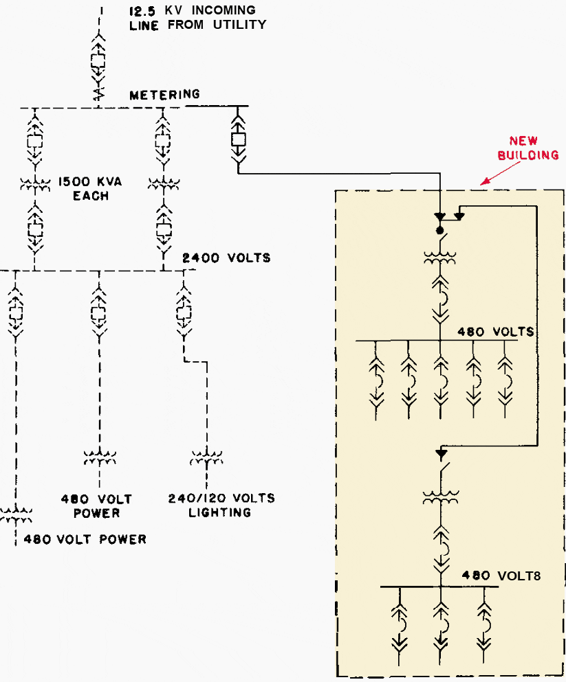
are plants where double transformation is used, for example, from 13.8 kV class voltage (utility supply voltage) to the 2.4 kV and from 2.4 kV to 480 V (Figure 11). When expanding such a system, the double transformation can be eliminated and power taken to the load centres at utility supply voltage and stepped down directly to 480 V (Figure 12).
Eliminating this double transformation will save about $4 to $15 per kVA in the cost of the power system. The double transformation may be necessary where the utility primary voltage is above 15 kV because voltages above 15 kV should not, in general, be taken into the buildings.
In some cases, such as at pumping stations where all but a very small amount of power is used at 2400 V, double transformation to 480 V may be justified.
Figure 11 – An existing power distribution system with the unnecessary double transformation of all power from 12.5 kV to 2.4 kV
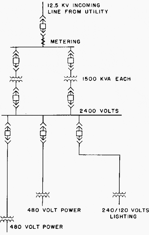

Figure 12 – Solid lines show expansion of the system shown in Figure 11, using the load-centre power distribution system in which power is stepped down directly from 12.5 kV to 480 V

Go back to the Contents Table ↑
4.3 Expanding Plant Power Generating Systems
There are many large plants in which considerable process steam is used and which, therefore, generate much of their own power. Many such plants have large low-voltage (600 V) systems or very large 2400 V systems. Expansion of such systems presents a real opportunity to change to a load-centre system and to higher voltage generation and thus to save money.
Examples will be used to illustrate the points involved. The following also applies where power sources are from transformers instead of generators.
Go back to the Contents Table ↑
4.4 Methods of Expanding at Higher Voltage
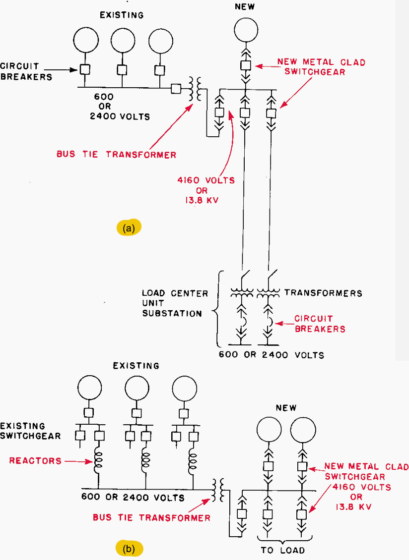
Expanding a low-voltage system at higher voltage is a simple procedure. It merely requires the addition of a bus-tie transformer between the buses. Then expansion can he to the higher voltage as if the lower voltage system did not exist. The old low-voltage and new high-voltage systems can be interconnected in several ways.
Figure 13 shows one method of employing a bus-tie transformer to connect a new system at higher voltage to an old system operating at a lower voltage. There may not be circuit breakers on both sides of the bus-tie transformer.
Figure 13 also shows the application of the bus-tie transformer where a synchronizing bus is used on the low-voltage system.
Figure 13 – Single-line diagram showing how a power system con be extended by adding new power sources at higher voltage and connecting in the higher voltage bus to the existing lower voltage bur through a transformer.

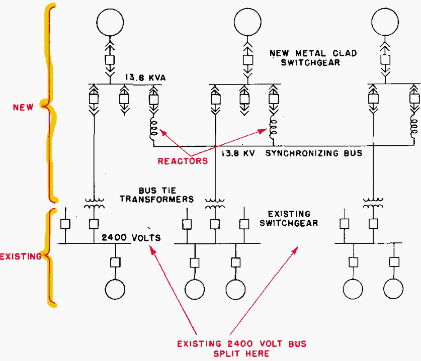
In a few cases, where there has been a very large expansion of a power system that necessitates the addition of a synchronizing-bus arrangement for the new high-voltage turbine generators, the arrangement shown in Figure 14 has been used.
The existing 2400 V bus is sectionalized. One section of the 2400 V bus is connected to each of the new high voltage buses through a transformer. This saves installing a synchronizing bus on the existing low-voltage system and permits circuit breakers to be employed on both the high- and low-voltage sides of the bus-tie transformers.
However, it might not be feasible to connect transformers to the synchronizing buses through circuit breakers in such large high-voltage systems because the duty on the synchronizing buses may be beyond the rating of available circuit breakers.
Figure 14 – Single-line diagram of a system in which the existing 2400V bus is sectionalized and connected through transformers to a new 13.8 kV system. The 13.8 kV system acts s synchronising bus for the 2.4 kV system.

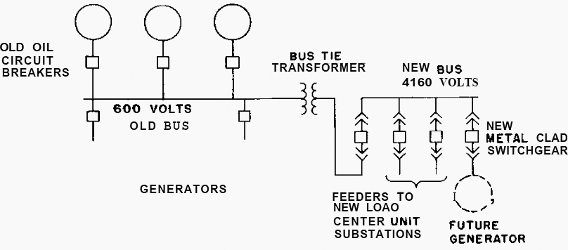
In some cases, it is desirable to establish a new higher voltage bus for supplying new load before a new higher voltage generator is added.
The arrangement shown in Figure 15 will enable this to be done at minimum cost. The new higher voltage feeders are fed through a step-up bus-tie transformer from the existing low-voltage bus. At a future date, a new generator may be added to the higher voltage bus. The load-centre system is employed for serving the new load.
Figure 15 – Existing 600 V bus extended at higher voltage through a bus-tie transformer to supply new load through load-centre unit substations before new higher voltage generator is added

Go back to the Contents Table ↑
Source: Industrial power systems by D. Beeman


When you know that the electrical substation it old? How many years means old? 1. Old for the tehnical safety function. 💡2 . Old for the electrical loses💰.
Too many old😀
Thank you.