
Benefits of PLC programmed logic
This technical article presents the modernization of a machine control system that will be changed from an old hardwired relay logic to PLC programmed logic. The field devices to be used will remain the same, with the exception of those that the controller can implement (e.g., timers, control relays, interlocks, etc.).
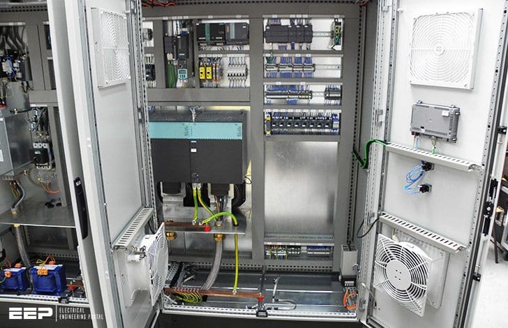 Modernizing An Old Hardwired Relay Logic With Modern PLC System
The benefits of modernizing the control of this machine are:
- More reliable control system,
- Less energy consumption,
- Less space required for the control panel,
- Flexible system that can accommodate future expansion
Electromechanical relay diagram
Figure 1 illustrates the relay ladder diagram that presently controls the logic sequence for this particular machine. For the sake of simplicity, the diagram shows only part of the total relay ladder logic.
An initial review of the relay ladder diagram indicates that certain portions of the logic should be left hardwired-lines 1, 2, and 3. This will keep all emergency stop conditions independent of the controller. The hydraulic pump motor (M1), which is energized only when the master start push button is pushed (PB1), should also be left hardwired.
Figure 2 illustrates these hardwired elements. Note that the safety control relay (SCR) will provide power to the rest of the system if M1 is operating properly and no emergency push button is depressed.
Furthermore, the PLC fault contact can be placed in series with the emergency push buttons and also connected to a PLC failure alarm.
During proper operation, the PLC will energize the fault coil, thus closing PLC Fault Contact 1 and opening PLC Fault Contact 2.
Continuing the example, we can now start assigning the real inputs and outputs to the I/O assignment document. We will assign internal output addresses to all control relays, as well as timers and interlocks from control relays.
Tables 1 and 2 present the assignment and description of the inputs and outputs, as well as the internals. Note // Inputs with multiple contacts, such as LS4 and SS3, have only one connection to the controller.
Table 1 – I/O address assignment
| I/O Address | ||||
| Module type | Rack | Group | Terminal | Description |
| Input | 0 | 0 | 0 | PB5 – Setup PB |
| 0 | 0 | 1 | PB6 – Reset (wired NC) | |
| 0 | 0 | 2 | PS1 – Hydraulic pressure switch | |
| 0 | 0 | 3 | SS1 – Enable selector switch (NC contact left unconnected) | |
| Input | 0 | 0 | 4 | SEL1 – Select 1 position |
| 0 | 0 | 5 | SEL2 – Select 2 position | |
| 0 | 0 | 6 | LS1 – Limit switch up (position 1) | |
| 0 | 0 | 7 | LS2 – Limit switch up (position 2) | |
| Input | 0 | 1 | 0 | LS3 – Location set |
| 0 | 1 | 1 | PB6 – Start load cycle | |
| 0 | 1 | 2 | LS4 – Trap (wired NC) | |
| 0 | 1 | 3 | LS5 – Position switch | |
| Input | 0 | 1 | 4 | PB7 – Unload PB |
| 0 | 1 | 5 | SS3 – Main/Backup (wired NO) | |
| 0 | 1 | 6 | LS6 – Maximum length detect | |
| 0 | 1 | 7 | LS7 – Minimum length detect | |
| Output | 0 | 3 | 0 | PL2 – Setup OK |
| 0 | 3 | 1 | PL3 – Select 1 | |
| 0 | 3 | 2 | PL4 – Select 2 | |
| 0 | 3 | 3 | SOL1 – Advance forward | |
| Output | 0 | 3 | 4 | SOL2 – Engage |
| 0 | 3 | 5 | PL5 – Engage ON | |
| 0 | 3 | 6 | M2 – Run motor | |
| 0 | 3 | 7 | PL6 – Motor run ON | |
| Output | 0 | 4 | 0 | SOL3 – Fast stop |
| 0 | 4 | 1 | PL7 – Fst stop ON | |
| 0 | 4 | 2 | SOL4 – Unload with backup | |
| 0 | 4 | 3 | PL8 – Backup ON | |
Table 2 – Internal address assignment
| Device | Internal | Description |
| CR1 | 1000 | CR1 (Setup Rdy) |
| TDR1 | 2000 | Timer preset 10 sec. register 3000 (accumulated register 3001) |
| MCR | MCR1700 | First MCR address |
| CR2 | – | Same as PL3 address |
| CR3 | – | Same as PL4 address |
| CR4 | – | Same as SOL1 |
| – | 1001 | To set up internal for instantaneous contact of TDR2 |
| TDR2 | 2001 | Timer preset 5 sec. register 4002 (accumulated register 4003) |
| – | 1002 | To set up internal for instantaneous contact of TDR3 |
| TDR3 | 2002 | Timer preset 12 sec. register 4004 (accumulated register 4005) |
PLC implementation
Figure 3 shows the PLC program coding (hardwired relay translation) for this example. This ladder program illustrates several special coding techniques that must be used to implement the PLC logic.
Among these techniques are:
- The software MCR function,
- Instantaneous contacts from timers,
- OFF-delay timers, and
- The separation of rungs with multiple outputs.
An MCR internal output, specified through the program software, performs a function similar to a hardwired MCR.
Referring to the relay logic diagram in Figure 1, if the MCR is energized, its contacts will close, allowing power to flow to the rest of the system. In the PLC software, the internal MCR 1700 accomplishes this same function (for this example, MCR1700 is the first available address for MCRs). If the MCR coil is not energized, the PLC will not execute the ladder logic that is fenced between the MCR coil and the END MCR instruction.
An internal will not replace the control relay CR2 in line 9 since the PL3 contacts in line 10 can be used instead. This technique can be used whenever a control relay is in parallel with a real output device. Moreover, we do not need to separate the coils in lines 17 and 18 of the hardwired logic. This has already been done, since the PLC used here does not allow rungs with multiple outputs. Using separate rungs for each output is always a good practice.
The normally closed inputs that are connected to the input modules are programmed as normally open, as explained in the previous sections. The limit switch LS4 has two contacts – a normally open one and a normally closed one in lines 17 and 19, respectively, of Figure 1.
However, only one set of contacts needs to be connected to the controller. In this example, we have selected the normally closed contact LS4. Although the normally open contact is not connected to the controller, its hardwired function can still be achieved by programming LS4 as a normally closed ladder contact.
Line 15 in the hardwired logic shows that, if PB6 is pressed and CR4 is closed, the timer TDR2 will start timing and contact TDR2-1 will seal PB6.
This arrangement requires special PLC implementation. If we use software timer contacts, the timer will not seal until it has timed out. If PB6 is released, the timer will reset because PB6 is not sealed. To solve this problem, we can use internal coil 1001 to seal PB6 and start timing timer 2001 (TDR2).
Lines 9, 10, and 11 of the PLC program coding show this technique. The time delay contacts (2001) are used for ON delays.
Resource // Introduction-to-PLC-Programming – www.globalautomation.info


Tôi rất thích
Thanks for d’inscription