
Estimated Study Time: 30 minutes
GIS operation & tricky situations
Over decades since its inception, GIS switchgear demand is still prevalent in these present times due to its compact built, reliability, and maintenance advantages compared to conventional Air-insulated switchgear. Even the strong negative effect on the environment when its gas is released into the atmosphere did not influence the GIS popularity.
 The most common Gas-Insulated Switchgear (GIS) faults and how to perform investigation
SF6 gas is used in this technology owing to its very high dielectric strength characteristics compared to conventional switchgear. When used at a certain pressure, it is, by far, one of the best options as an insulating and or arc-quenching medium.
Typical installation of this system is of the indoor type, thus reducing exposure of components to outside weather and corrosive atmosphere. Construction is modular with various standard designs of phase segregated type, or three-phase encapsulated type with minimal dimensions emphasizing its compactness and very reliable assembly.
This system utilizes Sulfur Hexafluoride (SF6) gas due to its outstanding dielectric properties for all parts insulation.
This article has been written by the author working in operation and maintenance of SF6 Gas Insulated Switchgear for a long time. It gives practical knowledge of the most common GIS faults and how to perform investigation and maintenance.
A case study of 220kV CB cubicle and an internal mechanical defect that could cause a potential switching disaster has been described in the last chapter.
- GIS Main Components
- The Most Typical GIS Faults
- A Case of Internal Mechanical Defect to Cause Potential Switching Disaster
- Conclusion
1. GIS Main Components
1.1 Circuit Breaker
GIS breaker is typically designed with a single pressure puffer type driven by a hydraulic operating mechanism at the front end. The grounded metal cylinder housing accommodates, in this case, a single pole interrupter fixed on an insulating mount and support insulator for each phase.
It is composed of moving and fixed sections, as shown in the figure. The moving section includes the nozzle, moving contact, moving arcing contact, the puffer cylinder connected to the hydraulic operating mechanism through an insulating rod, and its insulating support.
The fixed section comprises a fixed contact, fixed arcing contact, and mounting support.
The access cover on top allows GIS engineers to inspect and replace nozzles and arcing contacts.
Figure 1 – SF6 Gas Insulated Switchgear Circuit Breaker Chamber

Figure 2a – Cross-section drawing of a SF6 Gas Insulated Switchgear Circuit Breaker

Figure 2b – Cross-section drawing of a SF6 Gas Insulated Switchgear Circuit Breaker

Go back to the Contents Table ↑
1.2 Hydraulic Operating Mechanism
The three-pole typical operating box is generally located at the front of the circuit breaker. It houses the hydraulic operating mechanism and monitoring unit for individual single-pole operation of a circuit breaker.
The operating mechanism is composed of an oil pump, oil tank, main valve unit, pressure switches, and gauges, all arranged as one block unit and connected directly to the main cylinder making it a compact and more reliable hydraulic operating mechanism.
It’s essential to maintain the operating pressure of the hydraulic operating mechanism to operate the switchgear properly. Operating pressure for the GIS switchgear ranges typically from 30 to 40 MPa. A lower value will give an alarm command to the system.
Figure 3 – SF6 Gas Insulated Switchgear Hydraulic Mechanism (click to zoom)

Go back to the Contents Table ↑
1.3 Switch Disconnect / Earthing Switch
In this example, the line disconnector is housed along with the earthing switches emphasizing its compact build and simplicity. Both of these devices usually are motor or manually driven. The disconnector typically has a switching capability of bus transfer current. The bus disconnector is connected internally to each bus enclosure.
The earthing switch is normally provided with a motor-charged spring operation mechanism. Earthing switches which are normally installed at both sides of the circuit breaker, are linked together by an operating rod and can be operated by a common operating mechanism.
Earthing mechanism is equipped with a removable bolted link from the earth point to allow primary injection and other essential tests.
Figure 4 – SF6 Gas Insulated Switchgear Switch Mechanism
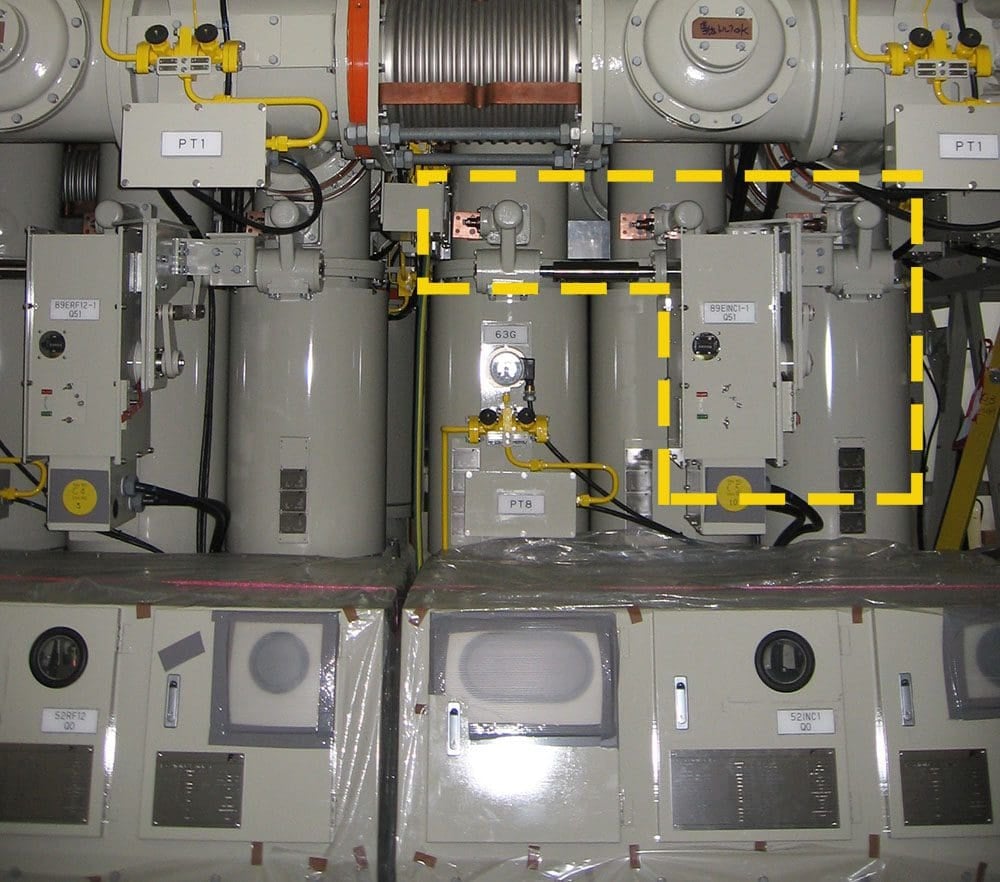
Figure 5 – SF6 Gas Insulated Switchgear Switch Mechanism
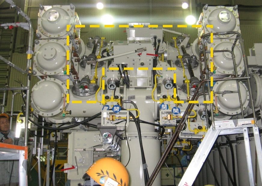
Figure 6 – Maintenance Earthing Switch Mechanism
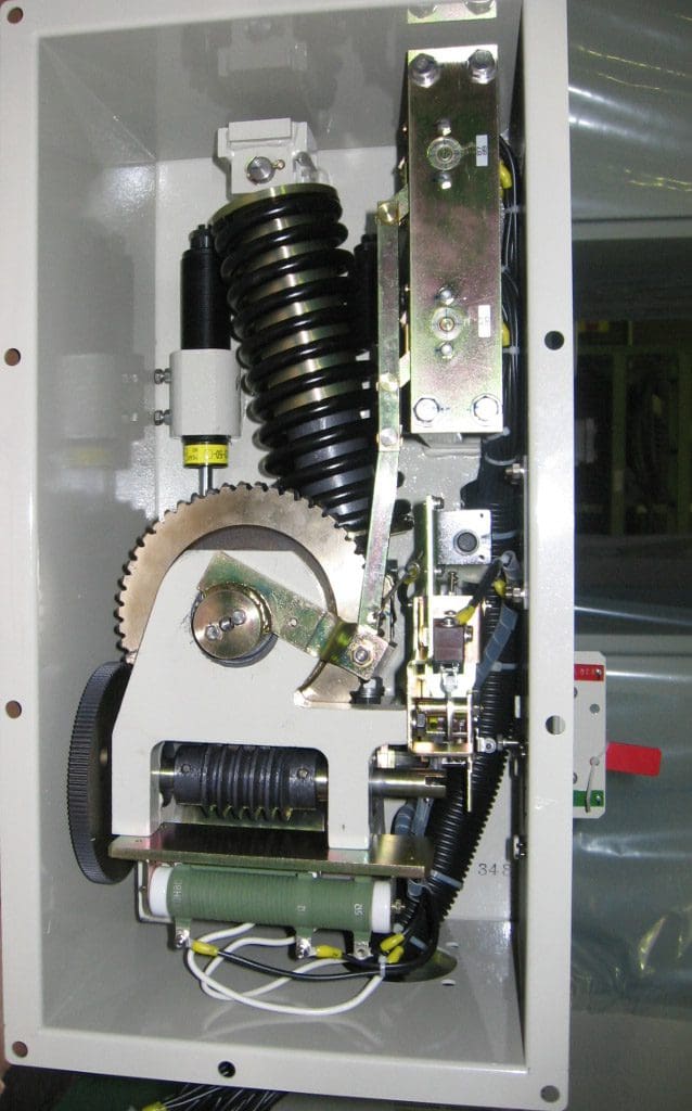
Figure 7 – Cross-section of a SF6 Gas Insulated Switchgear Switch Mechanism
Go back to the Contents Table ↑
1.4 Current Transformer/Voltage Transformer
The voltage transformer is the common induction type. The current transformer typically is a foil-insulated bushing type with a ring and a core mounted in CT housing. Insulation in the high voltage side is equipped with SF6 gas, and its winding discs use plastic foils for effective insulation.
Related electrical guides & articles


Lark C. Cosedo
A graduate of Bachelor of Science in Electrical Engineering from the University of San Carlos, Cebu, Philippines. Currently working as Electrical Senior Engineer at Oman Water and Wastewater Services Company (OWWSC), Sultanate of Oman. Currently holding a license as a Professional Electrical Engineer (PEE), an Asean Engineer (AER) and an Asean Chartered Professional Engineer (ACPE). I have more than 20 years of experience in the various fields of Electrical Engineering majority from the Middle East Regions comprising of Greenfield Aluminum Plants, Gov’t. Wastewater Services and Electronic Manufacturing Industry. Field of expertise are mostly from the Operation and Maintenance of Power Systems, Commissioning and start-ups, Operation and Maintenance Projects and Procurements. Possesses various Electrical Authorizations, currently as Senior Authorized Electrical Person (SAEP), H3 accreditation ranging from LV systems up to 220kV HV systems and with Accreditation for Safe Operation and Maintenance of HV systems from Faraday Institute, Cyprus.Profile: Lark C. Cosedo
