
Estimated Study Time: 21 minutes
SCADA, RTUs, IEDs and PLCs
Electrical distribution systems comprise a large number of remote applications and locations, and it has traditionally been challenging to monitor and regulate these remote applications and sites. Utility companies have been installing remote terminal/telemetry units, often known as RTUs, at substations in order to alleviate this issue.
 Three most common SCADA applications in MV/LV distribution systems you SHOULD know
In the beginning, remote terminal units (RTUs) were initially custom-made equipment; however, later versions depended on conventional hardware like as programmable logic controllers (PLCs) or industrial personal computers (PCs). Intelligent electronic devices, also known as IEDs, can be found placed at the majority of substations.
In most cases, these IEDs interact with the RTU located in the substation.
Switchgear feeders are in charge of controlling the distribution of power to the various electrical loads found in substations and electrical systems. A variety of data, including information on current, voltage, power, and the health of the switchgear, is collected by sensors that are positioned on the switchgear. These data are then sent to the RTU, which is followed by a SCADA system performing a polling operation.
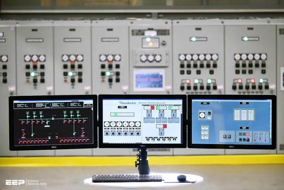
In order to monitor and regulate the activities of the substation and the equipment associated with it, operators look at the information displayed on the HMIs. Modern SCADA systems are exceptionally capable of managing the massive volumes of data that are required to monitor the electrical state of all power lines, connections, and equipment.
Let’s get into the discussion starting with introduction to SCADA systems operating in MV and LV distribution systems.
1. SCADA in MV/LV Distribution Systems
Medium voltage and low voltage distribution systems can have a number of different configurations, including the major ones, such as standard radial, double-radial, open-ring, and closed-ring. The amount of reliability required and the importance of the loads determine which design is chosen.
Consequently, manual or automatic switching of the system occurs under emergency operating situations, depending on the allowed duration of interruption periods and, of course, the nature of loads. In most cases, automation of the distribution networks serving industrial and commercial loads is required.
How much flexibility do we have in determining the extent to which distribution systems can be automated? That’s a good question, isn’t it?
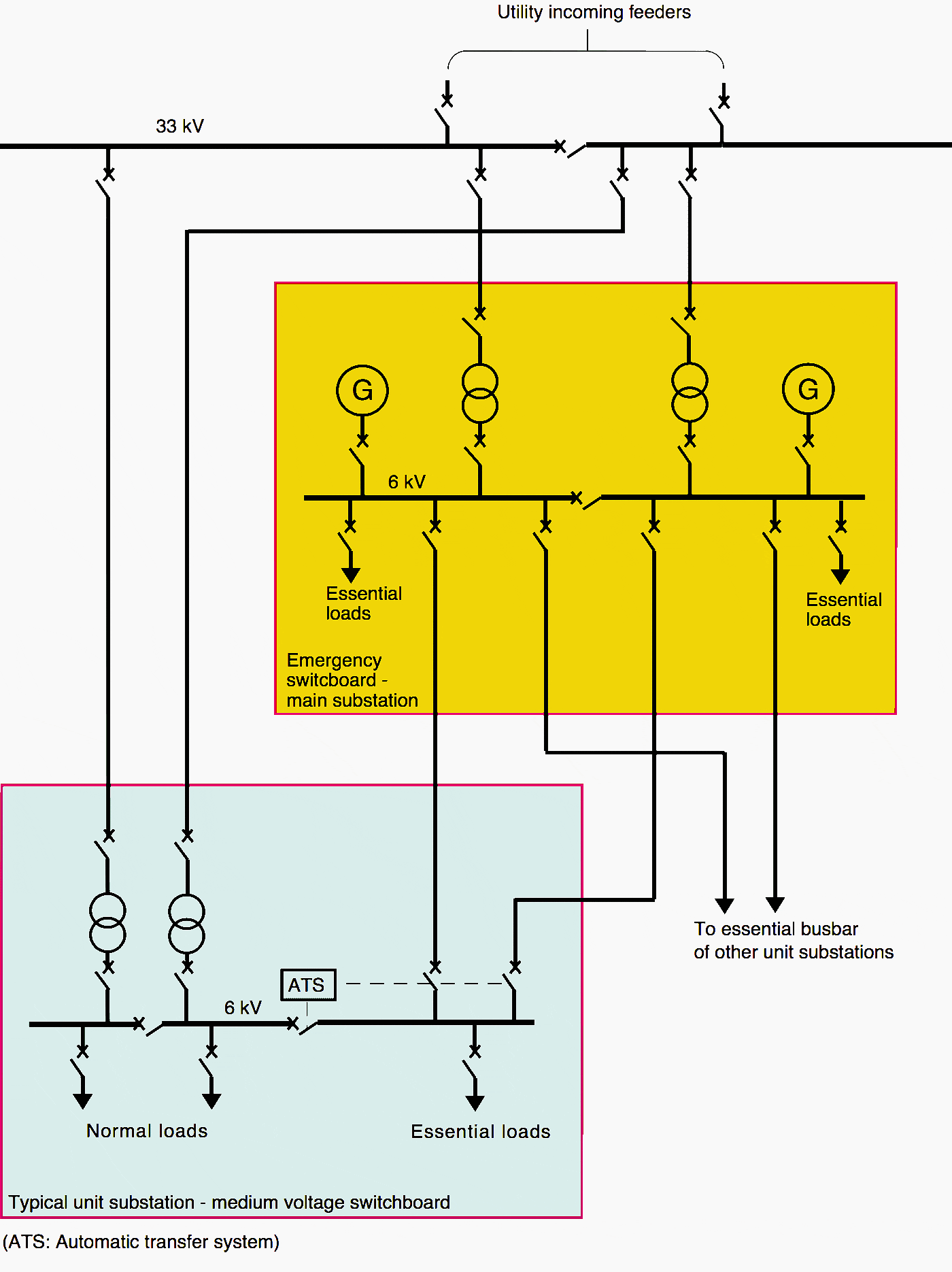
Figure 1 – Typical regular and emergency power supply for industrial plants
Network scale, load characteristics, and system hardware all play a role. Is it possible to fully automate a distribution system so that it functions reliably, efficiently, and safely even as it expands and becomes more complex?
The following discussion is an attempt to answer this topic.
This sub-switchboard supplies each unit on a floor with electricity as measured by individual utility meters. Standby generators must be installed as a backup to the utility supply to protect against the unpredictability of utility power and the potential for harm in the case of a power outage.
To avoid accidental paralleling, a CB interlock between the generators and the utility feeder is required. In addition, transfer switches must be installed on each level so that the power from the standby generator may be distributed directly to the apartments, bypassing the utility meters.
See Figure 2.
Figure 2 – Schematic drawing of main lines of feeding a commercial building
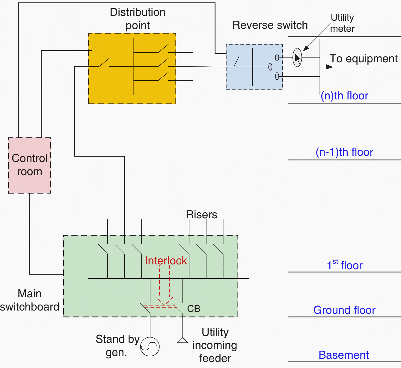
As a result of these demands, a great deal of apparatus must be dispersed across the building, including an interlock panel for each generator near the main switchboard (utility switches) in the control room, a transfer-switches panel near the sub-switchboard on each floor, and conduits connecting the apparatus to the control room.
The control room, naturally, will need a lot of room, and there will be a lot of wires connecting panels and distant sites. The state of the system during a power loss can be visually assessed by the operator from the control room, where he or she also monitors equipment functioning and functionality.
Related electrical guides & articles


Edvard Csanyi
Hi, I'm an electrical engineer, programmer and founder of EEP - Electrical Engineering Portal. I worked twelve years at Schneider Electric in the position of technical support for low- and medium-voltage projects and the design of busbar trunking systems.I'm highly specialized in the design of LV/MV switchgear and low-voltage, high-power busbar trunking (<6300A) in substations, commercial buildings and industry facilities. I'm also a professional in AutoCAD programming.
Profile: Edvard Csanyi
