
Estimated Study Time: 44 minutes
Switchgear Type Tests
Let me put the definition of switchgear type tests this way. A switchgear MUST withstand voltage in normal and abnormal conditions and to carry varying load currents during its lifetime. A switchgear MUST be able to clear faults occurring due to various unavoidable reasons and to carry fault current in case of through-faults. Type tests are the proof that a switchgear can fulfill all these requirements.
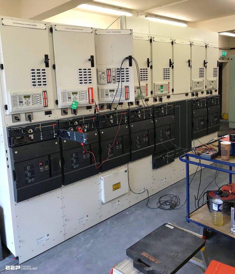 The most common type tests for medium voltage switchgear required from customers
As a result of all this, the switchgear MUST safeguard power system from severe damage while also being safe for operating workers and other equipment in the case of a breakdown in the switchgear panel.
The performance of a switchgear in normal and abnormal situations MUST be confirmed by subjecting it to various types of tests, the parameters for which are outlined in National and International standards in order to cover as many practical scenarios as feasible. Equipment testing begins with the idea stage, when the maker examines all conceivable parameters to ensure the equipment’s long-term performance.
The truth is that it’s pretty tough to establish all of the needs for all utilities or customers in one location. They can now choose between numerous types of equipment for different voltage levels and specifications, such as IEC 62271-100 and IEC 62271-200. However, the customer must inspect the site to determine how the test requirements will differ for the optimal equipment performance.
The number of test samples provided in IEC 62271-100 should be used for all type tests.
- Dielectric Tests
- Radio Interference Test
- Measurement of the Resistance of Main Circuit
- Temperature Rise Test
- Short-Time Current Withstand Test
- Verification of the Degree of Protection Test
- Electromagnetic Compatibility (EMC) Test
- Mechanical Operation Tests at Ambient Temperature
- Short-Circuit Duties Test
- Capacitive Current Switching Tests
- Environmental Test
- Critical Current Test
- Short Line Fault Test
- Out-of-Phase Making and Breaking Tests
Switchgear Type Tests
1. Dielectric Tests
The power system experiences occasional temporary power frequency overvoltages, which arises during load throw, wrong transformer OLTC operation, insufficient shunt compensation, resonance, etc. Dielectric tests are performed to verify the rated insulation strength of the switchgear to ascertain that when a circuit breaker is put into service, its design is capable of withstanding overvoltages occurring due to above reasons and due to lightning, switching operations, etc.
This is verified in compliance with the Standards. The tests which are performed under this category are discussed below.
1.1 One-Minute Dry-Power Frequency Voltage Withstand Test
This test is carried out to verify the capability of the equipment to withstand the power frequency test voltage for one minute in dry condition. The values of power frequency test voltage with respect to the system voltage have been identified in the standards.
1.2 One-Minute Wet-Power Frequency Voltage Withstand Test
This is the same as the one minute dry power frequency voltage test, but is conducted with equipment in wet condition. These are applicable for outdoor installations only.
1.3 Lightning Impulse Voltage Dry Withstand Test
This test is conducted to verify whether the switchgear is able to withstand overvoltage due to the peak value of standard impulse (1.2/50 μs) during lightning.
Figure 1 – Application of the impulse withstand

1.4 Switching Impulse Voltage Test (Optional)
This test is optional. It’s conducted to verify whether the switchgear is able to withstand overvoltages due to switching surges. This test is significant for system voltages above 300 kV.
Switching surges are comparatively of a longer duration (2500 μs), lower rate of rise and are represented by standard switching impulse test wave of 250/2500 μs.
1.5 Partial Discharge Test (Optional)
Partial discharge test is a component test and is not recommended to be carried out on complete switchgear, wherein the design of the switchgear consists of a combination of conventional compose. (e.g. CTs and VTs) which can be tested in accordance with their respective Standards.
But in the case of switchgear wherein organic insulating material is used, then this test is recommended, such as in the case of integrated switchgear design, specially GIS, where live parts and connections are embedded in solid insulation.
Suggested reading – Why is continuous on-line monitoring of partial discharge in the switchgear necessary?
Why is continuous on-line monitoring of partial discharge in the switchgear necessary?
1.6 Artificial Pollution Tests
These tests are applicable for outdoor installations only and are carried out on the basis of an agreement between the user and the manufacturer. The voltage values for the above tests are specified in standards against the system voltage.
1.7 Switchgear Design Aspects
While designing a switchgear, the parts located at different electric potential MUST be separated by insulation in order to ensure the safety of personnel working on it and the reliability of its operations, to prevent phase-to-earth, or phase-to-phase flashover.
The insulation in switchgear serves three main purposes. It provides insulation:
- Between current-carrying live parts and earth;
- In contact gap during ‘breaker open’ condition; and
- Between current-carrying live parts of different phases.
1.7.1 Gaseous Air
Gaseous air is the most commonly used gaseous material, which is composed of 80% nitrogen and 20% oxygen. Its properties are therefore close to nitrogen. Air clearances between phases and between phases to earth against the system voltage are as mentioned to IEC 62271-100.
Among gases, air is the only insulating material which can be used effectively at atmospheric pressure.
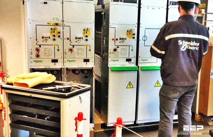
Figure 2 – Medium voltage (SF6 gas insulated) switchgear
1.7.2 Fluids
A range of fluids has been used for insulation in switchgear. Hydrogen carbon oil often referred to as ‘transformer oil’ was being used in bulk oil CB. It has the advantage of fulfilling the dual role of both an insulation as well as an arc-extinguishing medium. Its dielectric strength is three times that of SF6 at atmospheric pressure.
However, it is now coming under increasing scrutiny from the safety point of view because of its inflammable property. So, it’s not an option any more!
Related electrical guides & articles


Edvard Csanyi
Hi, I'm an electrical engineer, programmer and founder of EEP - Electrical Engineering Portal. I worked twelve years at Schneider Electric in the position of technical support for low- and medium-voltage projects and the design of busbar trunking systems.I'm highly specialized in the design of LV/MV switchgear and low-voltage, high-power busbar trunking (<6300A) in substations, commercial buildings and industry facilities. I'm also a professional in AutoCAD programming.
Profile: Edvard Csanyi
