
Estimated Study Time: 25 minutes
GIS Post-Installation Tests
This technical article explains some of the recommended and most important tests that MUST be performed on the Gas-Insulated Substation after the installation. Such tests are visual inspections, testing for control of cables, bus leakage and gas quality checks, main circuit resistance measurement, mechanical switching checks, interlocking checks, grounding measurements, and instrument transformer tests.
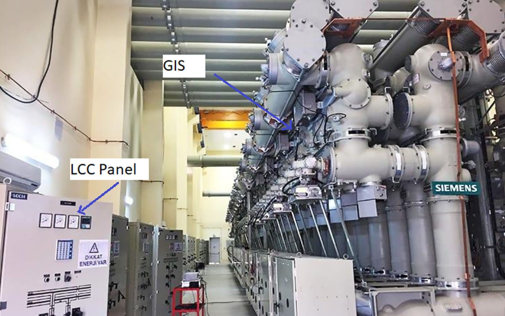
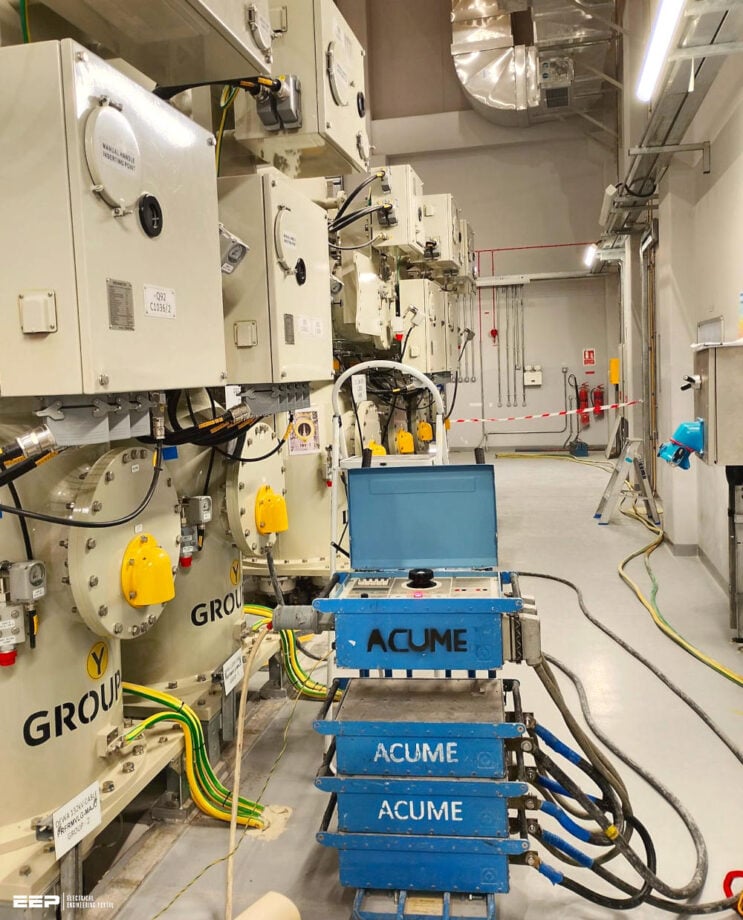 The Most Important Post-Installation Tests of a Gas-Insulated Substation - GIS (photo credit: Tamil Vendhan via Linkedin)
From the safety point of view, the testing & commissioning of distribution and transmission plants is often done under hazardous conditions. The risk of accidents must always be taken into consideration and the testing & commissioning personnel have to be fully aware of the dangers that exist and should know how to conduct their work to avoid such hazards.
The testing & commissioning of plant quite often has to be accomplished within a very short space of time and with many people from different companies involved.
There are two potential reasons for accidents which testing & commissioning personnel must take into consideration:
- Stressful situations where action goes before methodic thinking.
- Stressful situation during the energizing sequence etc. when one party is unaware of the actions taken by the other.
The testing & commissioning personnel must never allow themself to be influenced by customer demands (economic pressure) etc. which can jeopardize the safety of personnel.
Directives regarding the taking of measurements and any required fault-finding procedures in energized equipment, are to be given by Manufacturer’s chief commissioning engineer in order to minimize the risk of accidents which can occur when uncertainty arise as to who does what.
All personnel in the vicinity of the plant must be fully informed of the risks, which are present when auxiliary circuits of the plant are energized.
Ok, let’s dive into the details!
- A MUST Construction Visual Inspections
- Checking Control Cables and Wirings
- Bus Gas Leak Checks
- Gas Density Monitor and Local Alarm Tests
- Primary Circuit Resistance
- SF6 Gas Quality Tests
- Circuit Breaker Tests:
- Ground and Disconnect Switch and Circuit Breaker Interlock Tests
- High-Voltage Bus and Equipment Conditioning Tests
- Instrument Transformer Tests
- Other GIS Tests/Records:
- Attachments (DWG) 🔗 AutoCAD Drawings of Switching Single-Line Diagram and Interlocking Table for 380kV GIS Switchgear
1. A MUST Construction Visual Inspections
These tasks MUST include:
- Check all bonding and grounding conductors are installed, connected, and tight.
- Check the condition of the gas valves for normal operations.
- Inspect the appearance and condition of the primary GIS, for example, damaged paint, construction scraps, tight structure support connections, viewport covers, and so on.
- Cleanliness of the circuit breaker cabinet, disconnect and ground switches, and marshaling and local control cabinets.
- Equipment labeling including nameplates and device identification plates.
- Overall job site appearance and cleanliness.
- Condition of safety equipment, including fire extinguishers, first aid kits, and eyewashes.
Figure 1 – Sulfur Dioxide (SO2) Testing for SF6 Gas Quality
2. Checking Control Cables and Wirings
Typically control cable tests are in two categories. First, the insulation integrity is tested using a 1000 volt source (Megger), which may be manual or motorized. The owner or manufacturer should be consulted for a site-specific procedure; however, the objective is to confirm that individual conductors are insulated from each other and the cable shield, if one is present.
The cable jacket integrity is also tested. The objective is to detect missing or damaged insulation. Successful tests should show high resistive readings.
The installation crew should maintain records of the insulation tests and the point-to-point wiring checks. It is also a generally accepted procedure to trace the various protection, control, interlocking circuits, etc. during the point to point checks, and “yellow line” the associated electrical wiring or schematic drawings as the checks are made to verify the secondary circuit integrity.
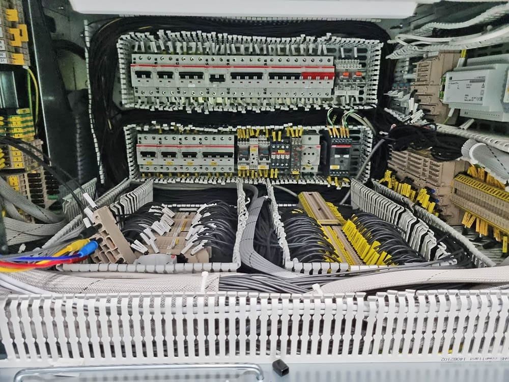
Figure 2 – Here we see the control cabinet of a GIS substation bay protection cabinet. This particular cabinet is equipped with an IEC61850 protection network.
3. Bus Gas Leak Checks
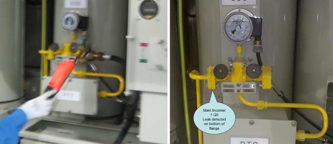
Once the various GIS compartments have been processed and gas-filled, a second leak check may be recommended by the manufacturers, particularly for long bus runs. Each flange is covered by plastic and sealed with duct tape. A small stone is placed in the bottom of the plastic “bag.” This plastic “enclosure” remains for 12 to 24 hours.
An SF6 detection device is then inserted into the bag. If there are gas leaks, as SF6 is heavier than air, it will settle to the bottom of the plastic bag (see Figure 3) and activate the detector.
Figure 4 shows example of using SF6 gas detector.
Figure 3 – Flange gas leakage test
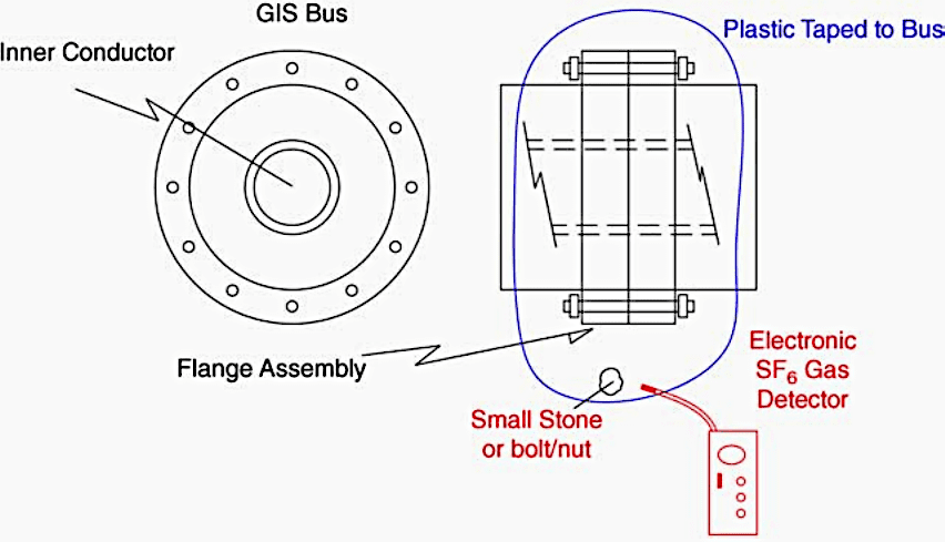
Figure 4 – Gas zone leakage detectors
4. Gas Density Monitor and Local Alarm Tests
This test involves keeping the gas density monitor wired but isolated electrically with open terminal block slide links or a similar switch mechanism, before mechanically isolating the density switch using appropriate valves. Bleed a small amount of gas off and using an ohmmeter at the terminal block, observe and record the alarm point.
Two-way radio or a similar communication may be required for large installations. In a similar manner slowly introduce some gas and as the pressure rises, observe the density switch reset point.
The test purpose is to verify the final wiring and actual alarm points.
5. Primary Circuit Resistance
Generally this test requires a 100 A DC μΩ meter with independent voltage and current sources. Tests are conducted on an assembled GIS section as specified by the manufacturer, isolating the circuit using a ground switch and removing its grounding strap.
The various GIS switches in the test circuit are configured to meet the measurement requirements, and with the current lead connected to the “floating” ground strap and the μΩ meter voltage lead connected to the ground switch enclosure, 100 A are injected into the circuit. The readings obtained are compared to engineering calculations, which may include a tolerance specification.
An acceptable field measurement agrees with the engineered calculation.
Suggested Guide (PDF) – Electrical Testing and Commissioning Handbook
6. SF6 Gas Quality Tests
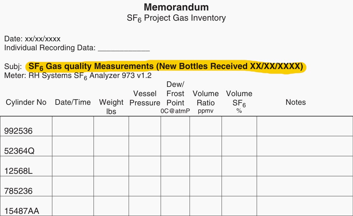
Once the gas compartments are processed and filled to the correct pressure/density, gas purity tests are conducted (see Figures 5 and 6). These tests require a small amount of gas and identify the level of moisture present and the purity of the SF6. For new GIS equipment installations acceptable values are moisture levels in the 150 ppm to 300 ppm range and gas purity in the 99.5% range.
Some manufacturers decrease the acceptable parameters in older or reprocessed gas to 500 ppm moisture with a gas purity of 98%. These values should be recorded for maintenance baseline use when gas quality measurements are made in the future.
A table similar to Figure 5 should be prepared to record the individual gas zone SF6 moisture content and purity for future maintenance baseline comparison purposes.
Figure 5 – SF6 project gas inventory
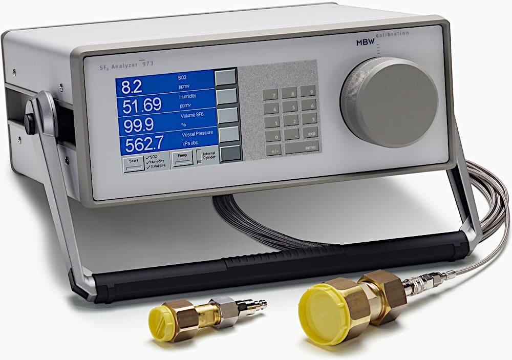
Pure SF6 serves as the typical filling in GIS; nevertheless, gas compartments can get contaminated with water vapor (H2O) over time due to absorption and desorption from interior materials. Although water vapor and SF6 typically do not interact, under high-energy discharge conditions, hydrogen and oxygen dissociated from water vapor will react with sulfur and fluorine from SF6, resulting in the formation of breakdown by-products.
These comprise sulfur dioxide (SO2) and hydrofluoric acid (HF), which are corrosive to the inside components of gas compartments.
SF6 with minimal water vapor content substantially diminishes the likelihood of generating these corrosive chemicals, therefore rendering precise and consistent measurement data an essential component of any GIS preventative maintenance program.
Figure 6 – SF6 Gas Analyzer
7. Circuit Breaker Tests
Caution: before proceeding with any breaker operations tests, any closing or tripping prevention pins or lock devices should be identified. Depending on the test, the pins or lock devices may or may not be required.
The breaker operating pressures should also be verified to confirm and the circuit breaker is at full operating levels.
7.1 Mechanism Stroke, Wipe Measurement
These tests are generally performed at the factory and verified in the field to ensure that shipping or the installation procedure has not damaged the breaker mechanism or caused it to deviate from acceptable tolerance levels.
Manufacturers should provide the measurement technique and acceptable limits for both the stroke and main contact wipe.
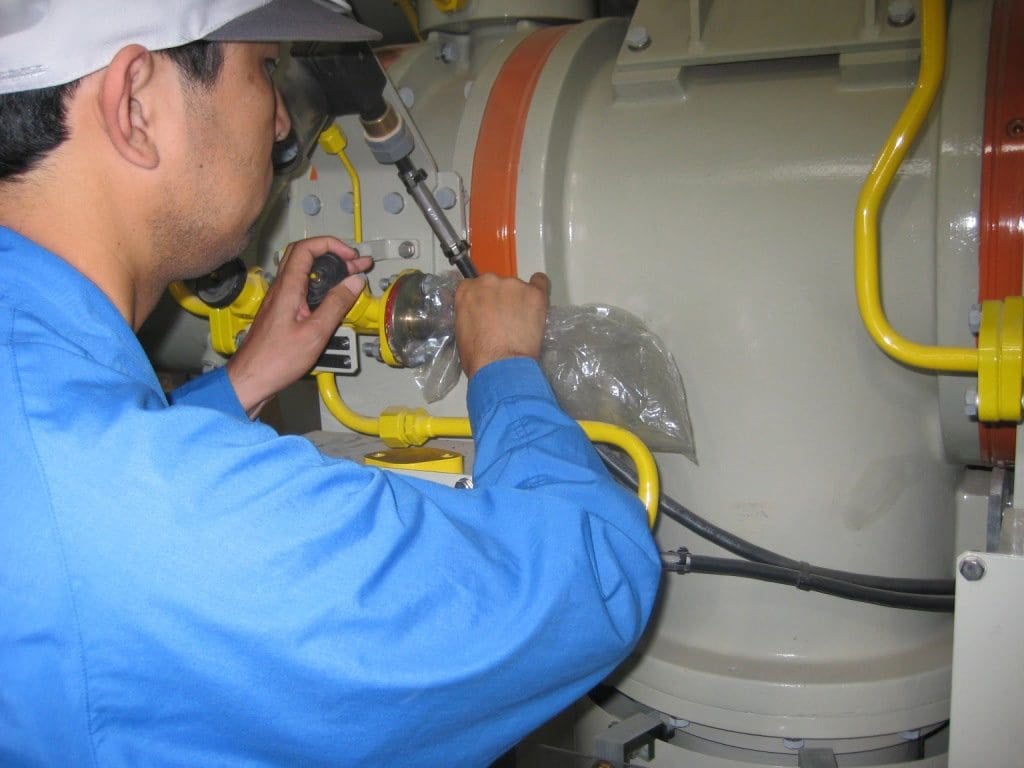
This set of measurements is usually done when operating the circuit breaker manually (see Figure 7).
Figure 7 – Circuit breaker stroke measurement
7.2 Open/Close Operation Including Anti-pumping
This test will confirm whether the circuit breaker properly opens and closes. One manual test is performed and then the necessary open and close operations at the operating control voltage, as identified in the specification, for example, open and close “X” times in a specified time.
The objective is to observe whether the lights and indicators work properly and the owner’s specification requirements are met.
Watch Video – Circuit Breaker motion measurement on a B65-145 GIS
The anti-pumping test involves closing and opening the breaker with a continuous signal on the close coil. If the anti-pumping circuit is properly functioning, the breaker should not re-close until the close coil is de-energized.
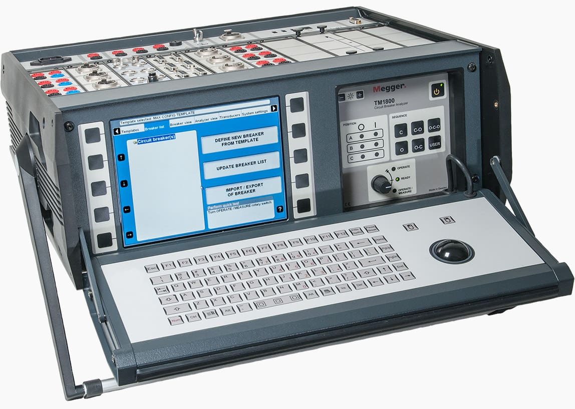
7.3 Breaker Travel and Timing Test
These tests are to confirm the dynamic operating performance of the breaker by measuring the operating times on a per pole basis and identifying any discrepancies or deviations with the phases. Manufacturers will typically provide the timing range and the maximum phase discrepancy limit. Any readings outside the manufacturer’s stated values should be investigated and adjustments made as necessary.
Figure 8 is typical instrumentation used to check circuit breaker contact timing.
Figure 8 – Circuit breaker time and travel analyser with DualGround™ testing by Megger
7.4 Low Gas Tripping and Block Close Operations
This test is on the circuit breaker gas system to prove whether gas leakage detection (multiple alarm levels) is operational and the control limits, for example, serious loss of gas, will block close and prevent the breaker operation.
The manufacturer usually confirms that the tests are acceptable before a circuit breaker is placed in service.
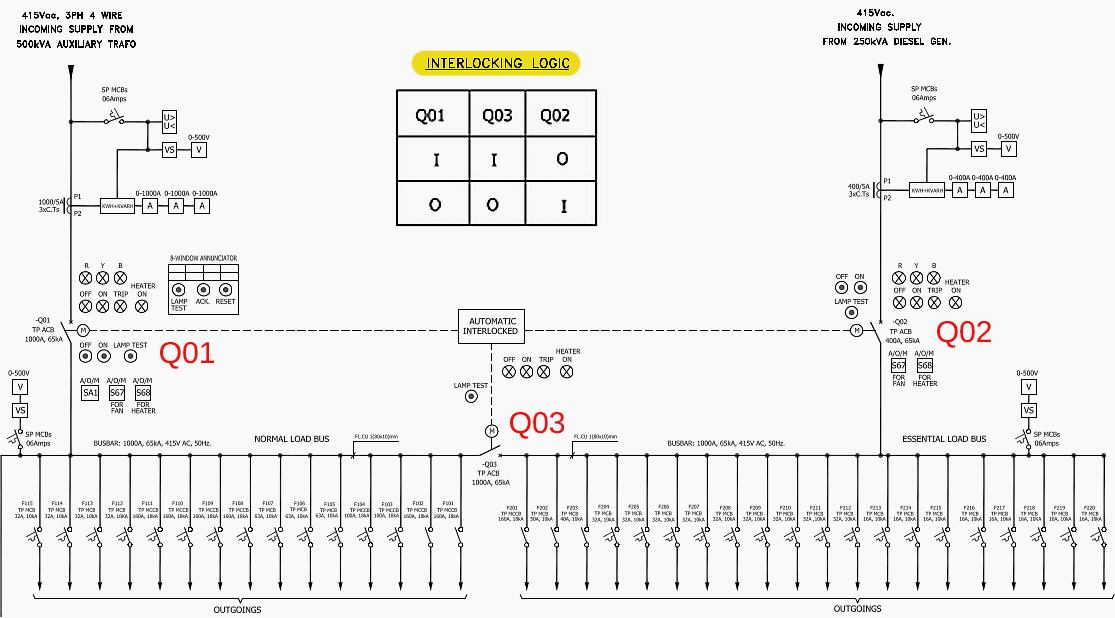
8. Ground and Disconnect Switch and Circuit Breaker Interlock Tests
GIS equipment is generally provided with interlocks to prevent incorrect operations; for example, most disconnects are not designed for load break operation and similarly ground switches cannot be closed without interconnected circuit breakers and disconnects open.
The manufacturer’s interlock logic diagram should be reviewed to verify the various open and close combinations and confirm that incorrect operations are blocked. These interlock schemes should also be checked for correct integration into the owner’s protection and switching logic.
Figure 9 – Logic Table for Interlocking Circuit Breakers in the AC Supply Panel
9. High Voltage Bus and Equipment Conditioning Tests
Before the GIS installations are placed in service, a high voltage conditioning test is performed with momentary voltages in excess of the equipment rated line-to-ground voltages. The objectives of the test are: to identify any abnormalities in the bus (loose hardware, tools, cleaning material inadvertently left in the bus) that could compromise the internal electrical clearances, identify excessive moisture levels and move conductive and semi-conductive materials to low stress areas or particle traps to prevent insulation flashovers.
The test voltage levels and time durations vary between manufacturers and are based upon the equipment voltage class, but for illustration purposes on a 362 kV class, 1050 BIL installation the test levels may be as shown in Table 12.
Table 1 – Test levels
| Step | Step (kV) | Time (s) |
| 1 | 100 | 20 |
| 2 | 125 | 15 |
| 3 | 175 | 10 |
| 4 | 225 | 2 |
| 5 | 275 | 1 |
| 6 | 300 | 1 |
| 7 | 325 | 1 |
| 8 | 350 | 1 |
| 9 | 400 | 1 |
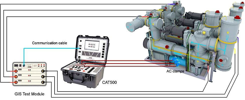
The high voltage test on site is usually done by a resonance test procedure. The inductance of the test transformer and the capacitance of the GIS are chosen in such a way that they form a resonance circuit in the range of 50–100 Hz.
This allows much smaller test equipment, which is shown in Figure 10.
Figure 10 – Variable Frequency high-voltage AC Resonant Test System
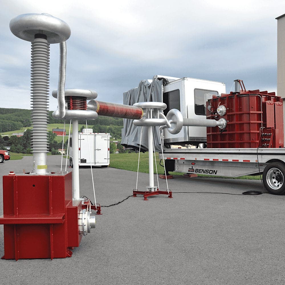
The benefits of using a series resonant test is the inherently limited fault current available, compared to a fault energy present when the GIS equipment is connected to the transmission system. A typical test on 362 kV equipment will take approximately an hour. A three person team is recommended including a safety observer, a timer, and the test set operator.
The substation or switchyard low voltage (120/208 v, 220 v, 380 v, 277/440 v) station service connections and capacity should be identified early in the project. If insufficient capacity is available for the test set, a small portable generator may be required.
The GIS can be tested in multiple ways. To expedite the process, one methodology is to test large bus sections at once, taking into consideration the test set capacity. The disadvantage of this approach is that if a discrepancy is identified, the test section will need to be sectionalized into smaller increments to isolate the problem area. A second approach is to begin with smaller test sections, but this will require more test time.
After a test failure, given the low energy involved using the test set, repeat tests can be performed to help isolate the problem. If possible the test section should be reduced with portions of bus systematically removed from the test, until the problem section is located. It may also be helpful to locate individuals at points along a bus to help locate the “ping” or audio noise that may occur when a flashover (test set trips) occurs inside the bus.
Personnel should be positioned in safe locations, well clear of the test set and its connections.
Watch Video – 560kVA 280kV AC Resonance Test Set Wiring Video
10. Instrument Transformer Tests
Current and voltage transformer tests include polarity, ratio, and current transformer saturation curves. These tests require voltage and current injection and are equivalent to testing conducted on similar air insulated equipment.
The results are compared to the manufacturer’s published data.
Further Study – Comprehensive Guide to Secondary Injection Testing of the Current Transformers (Part 1)
Comprehensive Guide to Secondary Injection Testing of the Current Transformers (Part 1)
Further Study – Comprehensive Guide to Secondary Injection Testing of the Current Transformers (Part 2)
Comprehensive Guide to Secondary Injection Testing of the Current Transformers (Part 2)
11. Other Tests/Records
11.1 AC Station Service Measurements, Heater & Control Cabinet Light Operations
This work involves checking the heater circuits for current with a clamp-on ammeter, observing correct light operations using a door or manual switch, confirming all power receptacles are operational, and checking for tight connections.
Ground fault protection should be provided for receptacles particularly if the local control or marshalling cabinet is located outdoors. Three phase 60 or 100 A disconnects with independent power sources located on the exterior of the local control or marshalling cabinets may also be convenient to connect welders or gas cart/processing equipment.
Thermostatic control settings (if used) should also be verified and the levels recorded.
Figure 11 – AC control circuits: heater circuit, AC load circuit, and lighting circuit (click to zoom)
Figure 12 – GIS local control cabinet
11.2 Final Circuit Breaker Counter Readings
Before equipment is made available for owner operations personnel, all circuit breaker counters are recorded and the values entered in the commissioning records.
11.3 Turnover Gas Zone Density Readings
In a similar manner, all gas zone pressures are recorded including circuit breakers on a compartment, per phase if an iso-phase bus is installed. The bus temperature is also recorded and the pressure reading temperature-compensated.
The value obtained is compared to the engineered nominal value with acceptable readings are within the engineered value.
The gas density gauge design should be discussed during the initial engineering discussions.
Further Study – Primary injection testing and CTs commissioning in power substations
Primary injection testing and CTs commissioning in power substations (for true engineers)
12. Attachments (DWG): AutoCAD Drawings of Switching Single-Line Diagram and Interlocking Table for 380kV GIS Switchgear
Download Attachments: AutoCAD Drawings of Switching Single-Line Diagram and Interlocking Table for 380kV GIS Switchgear (for premium members only):
Sources:
- Gas-Insulated Substations by Hermann Koch
Related electrical guides & articles


Edvard Csanyi
Hi, I'm an electrical engineer, programmer and founder of EEP - Electrical Engineering Portal. I worked twelve years at Schneider Electric in the position of technical support for low- and medium-voltage projects and the design of busbar trunking systems.I'm highly specialized in the design of LV/MV switchgear and low-voltage, high-power busbar trunking (<6300A) in substations, commercial buildings and industry facilities. I'm also a professional in AutoCAD programming.
Profile: Edvard Csanyi
