
Estimated Study Time: 14 minutes
PLC programs
PLCs from different manufacturers can be programmed in various ways. Popular programming languages for PLCs are ladder diagrams, Function Block Diagrams (FBD), and statement list. With a few exceptions, a program written in one format can be viewed in another.
 4 most popular PLC programming languages for implementation of control diagrams (photo credit: Green Mamba via Flickr)
Popular programming languages for PLCs
Let’s take the discussion on each of popular programming languages for PLCs:
1. Ladder Diagrams
As an introduction to ladder diagram, consider the simple relay circuit which contains a coil and contacts as shown in Figure 1.
When a voltage is applied to the input coil, the resulting current creates a magnetic field. The magnetic field pulls a metal switch (or reed) towards it and the contacts touch, closing the switch. The contact that closes when the coil is energized is called normally open (NO).
The Normally Closed (NC) contacts touch when the input coil is not energized. When the input coil is not energized, the normally closed contacts will be closed (conducting).
The relay arrangement can be shown with the help of different schematic circuits as shown in Figure 1.
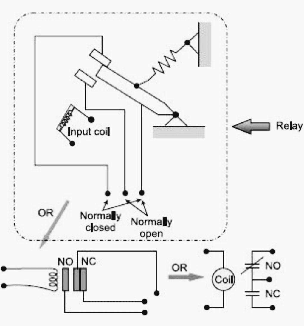
Relays are normally drawn in a schematic form using a circle to represent the input coil. The output contacts are shown with two parallel lines. NO contacts are shown as two lines, and will be open (nonconducting) when the input is not energized. NC contacts are shown with two lines with a diagonal line through them.
Now, if it is required to operate NO (C) contact of this relay, connected to an ac source, through two input relay contacts, A (NC) and B (NO) then the relay logic diagram shown in Figure 2 is the most appropriate for a typical logic.
According to the relay logic diagram shown in the figure, activation of the input relay coil corresponds to the contact B, makes C (output) closed and activation of the input relay coil corresponds to the contact A, makes C (output) to get opened.
This sort of arrangement is normally employed in conventional hard-wired relay logic circuit.
The same scheme can be implemented following ladder logic as shown in Figure 2. The ladder logic-diagram is the most commonly used method of programming PLCs. The ladder diagram consists of two vertical lines representing the power rails. Circuits connected as horizontal lines between two rails are called rungs of the ladder. Few symbols used to denote ladder logic inputs and outputs are shown in Figure 3 and 4 respectively.
Taking into consideration these ladder logic symbols, the ladder logic implemented in Figure 2 mimics the same hard-wired relay logic.
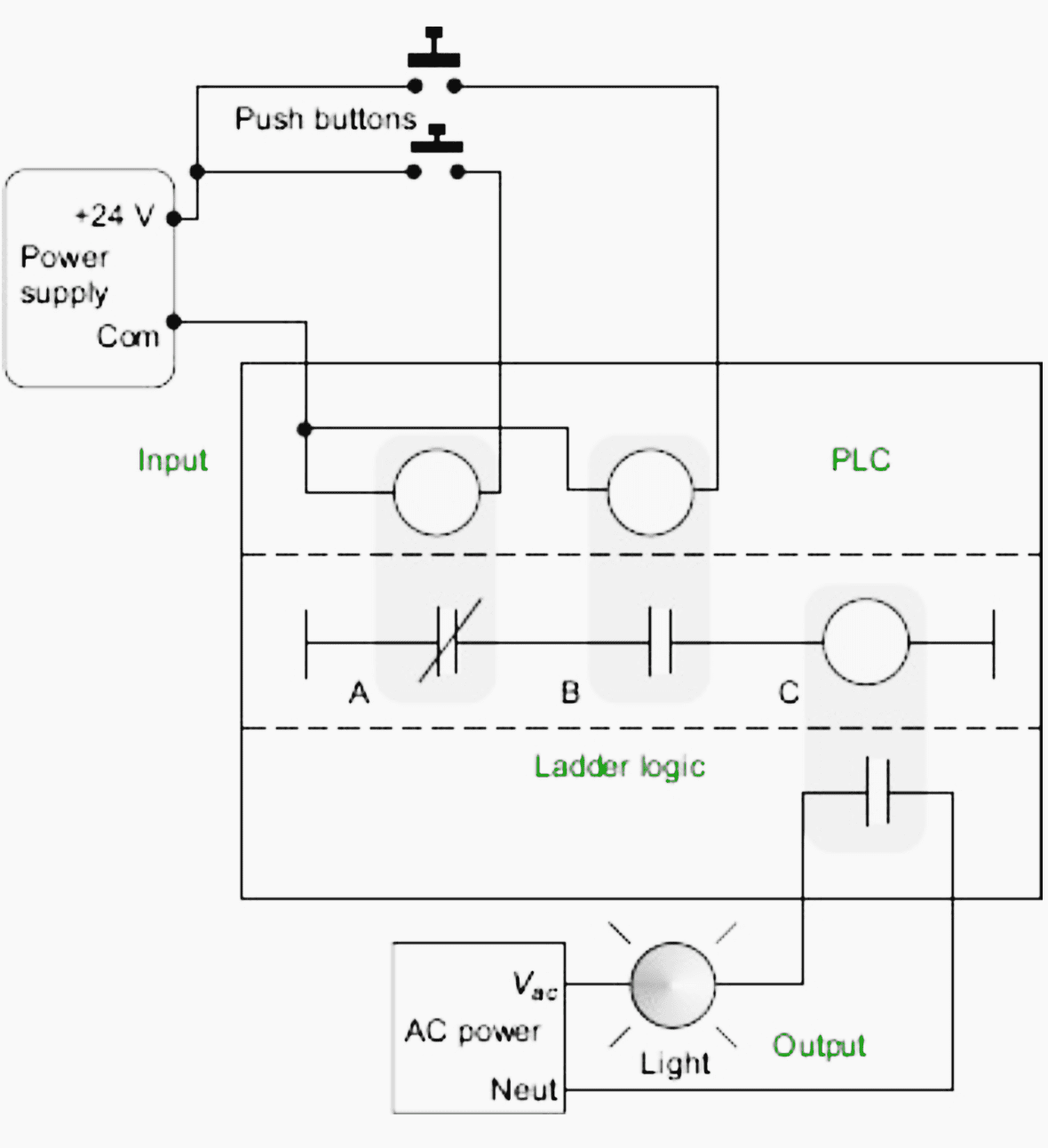
Finally, this ladder logic is inserted as a control program to a PLC where, input devices, and output devices are arranged in a fashion as illustrated in Figure 5.
So, the ladder-logic programs are loaded into the PLC, the input and output devices are connected to I/O modules and then the execution of the program updates outputs according to the status of inputs.
Many relays also have multiple outputs and this allows an output relay to also be an input simultaneously.
The circuit shown in Figure 6 is an example of this and it is called a seal-in circuit. In this circuit, the current can flow through either branch of the circuit, through the contacts labelled A or B.
Note! If A is closed, the output B will turn on, and input B will also turn on which will keep output B on permanently – until power is removed.
Another example of ladder logic can be seen in Figure 7. To interpret this diagram, imagine that the power is on the vertical line on the left-hand side, called hot rail. On the right-hand side is the neutral rail.
An output will be some device outside the PLC that is switched on or off, such as lights or motors. In the top rung, the contacts are normally open and normally closed, which means if input A is on and input B is off then power will flow through the output and activate it.
Any other combination of input values will result in the output X being off.
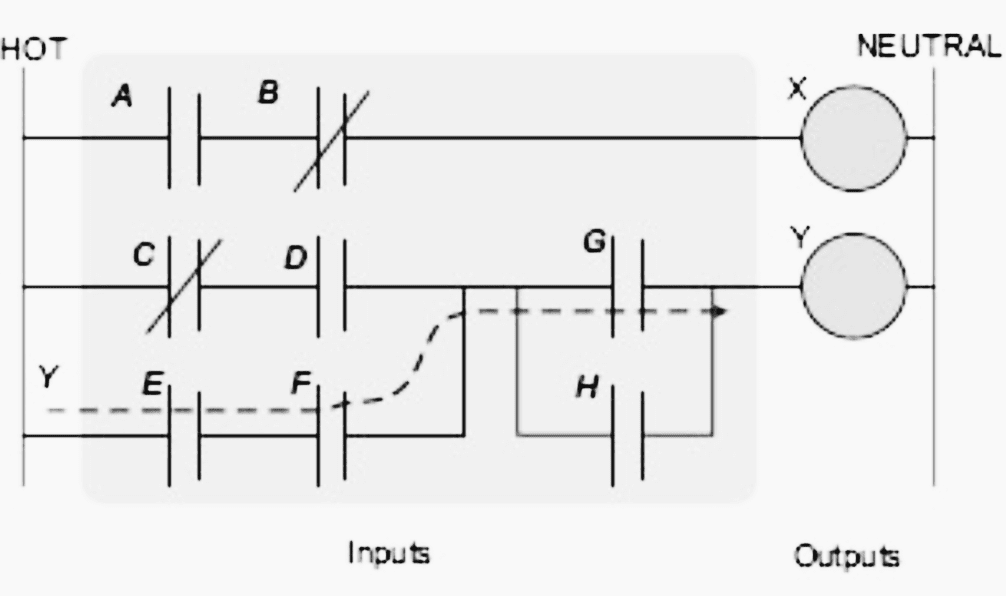
Note! Power has to flow through some combination of the inputs (A, B, C, D, E, E, F, G and H) to switch on outputs (X, Y)
Example //
Try to develop (without looking at the solution) a relay-based controller that will allow three switches in a room to control a single light.
Solution
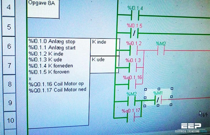
There are two possible approaches to this problem. The first assumes that any one of the switches on will turn on the light, but all three switches must be off for the light to be off. The ladder logic is shown in Figure 8.
The second solution assumes that each switch can turn the light on or off, regardless of the states of the other switches. This method is more complex and involves thinking through all of the possible combinations of switch positions.
You might recognize this problem as an exclusive or problem. The ladder logic is as shown in Figure 9.
Note! It is important to get a clear understanding of how the controls are expected to work. In this example, two radically different solutions were obtained based upon a simple difference in the operation.
Ladder Diagram Basics #1
Ladder Diagram Basics #2 (Safety Control Circuit)
Ladder Diagram Basics #3 (2 Wire & 3 Wire Motor Control Circuit)
2. Function Block Diagram
Function Block diagram (FBD) is used for PLC programs described in terms of graphical blocks. It is described as being a graphical language for depicting signal and data flows through Inputs blocks, these being reusable software elements.
Functional blocks can have standard functions, such as those of the logic gates or counter or timers or have functions defined by the user, e.g. a block to obtain an average value of inputs.
Function Block Diagram (FBD) programming – First lesson
In this video you will learn the basics of programming PLCs with Function Block Diagramming (FBD) language. FBD is a graphical language, in which you deal with the blocks and connection between the blocks.
How to create and use Function blocks in the project
In this video you will learn how to create customized function blocks in the project and call them in the main program.
3. Statement List
In statement-list programming approach, an instruction set similar to assembly language for a microprocessor is used. Statement lists, available on few brands of PLCs, are the most flexible form of programming for the experienced user but are by no means as easy to follow as ladder diagrams or logic symbols.
Figure 11 shows a simple operation in ladder-diagram form for a Mistsubishi PLC. The equivalent statement list would be as shown in Table 1.
How to use PLCSIM S7-300 STL LESSON 1 Tutorial
In this lesson we discuss about STL Program and concept of RLO&STA. Detailed information about RLO and STA is explained along with simulation.
PLCSIM S7 300 STL LESSON 2 Tutorial…automation in plant
In this lesson we will learn how to write a PLC program using an “S7 300” PLC and “STEP 7” software.
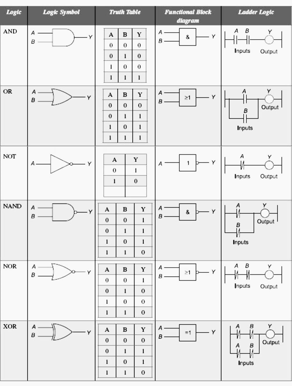
4. Logic Functions
There are many control situations requiring actions to be initiated when a certain combination of conditions is realised. Thus, for an automatic drilling machine, there might be a condition that the drill motor is to be activated when limit switches are activated that indicate the presence of the workpiece and the drill position as being at the surface of the workpiece.
The electric circuit, truth table, ladder diagram and functional block diagram for different logics are presented in Table 2.
Logic Gates vs Ladder Logic Circuits
Reference // Electrical and electronics measurements and instrumentation by Prithwiraj Purkait, Budhaditya, Santanu Das and Chiranjib Koley (Get paperback at Amazon)
Related electrical guides & articles


Edvard Csanyi
Hi, I'm an electrical engineer, programmer and founder of EEP - Electrical Engineering Portal. I worked twelve years at Schneider Electric in the position of technical support for low- and medium-voltage projects and the design of busbar trunking systems.I'm highly specialized in the design of LV/MV switchgear and low-voltage, high-power busbar trunking (<6300A) in substations, commercial buildings and industry facilities. I'm also a professional in AutoCAD programming.
Profile: Edvard Csanyi

Awesome post.
Pls sir I need your WhatsApp contact as I have many things to learn
Very nice information
Kindly advise me on the best computer programming language courses one can take to help me do industrial programming well being an instrumentation and control engineering student
Hi
I am beginner in PLC.
I think Table 2 has mistake in ladder logic XOR, it has to be |—-||—-|\|—–o—|
A B
|—-||—-|\|—-
B A
Kind regards
Talat
You are right
GOOD thanks!
Very useful and knowledgeable topics.
SFC-sequential flow chart also better
Nice article Eddy Sir.
Please correct the ladder logic of XOR gate. In each rung , one must be NO and the other must be NC.