Star-delta (Y-Δ, wye-delta) starting
Star-delta (in North America the designation “wye-delta” is commonly used instead) starting is the simplest method for reducing the starting current of a motor. The technique can be used with all squirrel-cage induction motors that are delta-connected for normal operation and whose windings ends are individually connected to terminals.
The reduction of the motor current causes a reduction of the starting torque.
Transient currents
When the delta contactor connects at adverse vectorial positions of the supply voltage and the rotor field, transient processes could occur in the motor that could lead to larger current peaks than at switching-on the delta-connected motor.
This can result in the making capacity of the contactors being exceeded with as a consequence welding of contacts.
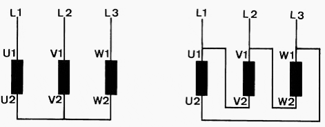
The transient currents can be reduced by appropriate wiring of the main circuit (Figure 1). Besides the load on the contactors, this also reduces the dynamic stress on the windings-heads in the motor.
Lower transient currents peaks with correct wiring
Clockwise rotation
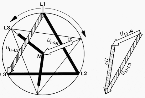
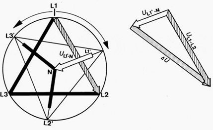
During the de-energized switching interval, the rotor falls back against the rotating field of the power supply. Its magnetic field induces a decaying residual voltage in the stator – in the voltage phasor diagram Figure 2 for the pole conductor L1 entered as UL1’-N.
When connecting to delta (Fig. 1 and Fig. 2) the mains voltage UL1-L3 is applied to the stator winding, across which this residual voltage is still present. The differential voltage ∆U is relatively small, thanks to the favorable vectorial position of the residual voltage UL1’-N and the supply voltage UL1-L3 that are approximately oriented in the same direction.
Thus the current surge generated by this resultant voltage will also remain small.
High transient current surge with incorrect wiring
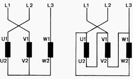
The motor also turns clockwise when the terminals are connected according to Figure 3.
A decaying residual voltage acts again with lagging phase position in the stator during the switching interval. On switching to delta, the phase winding with the phasor UL1’-N is connected to the supply phase UL1-L2. These two voltages however have totally different vectorial directions, the differential voltage ∆U is high and results in a correspondingly high transient current surge.
Switching from star to delta produces the phasor diagram Figure 4.
Counterclockwise sense of rotation
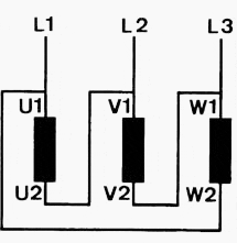
To run the motor in the counterclockwise direction, it is not enough to swap around two phases at any point. This would produce the same relationships as described above. In order to keep the transient current surge from star to delta connection as small as possible the wiring must be arranged as in Figure 5.
Reference // Low-Voltage Switchgear and Controlgear – Allen-Bradley (Download here)


Hi I have a bending machine 380v 50hz here we do not have 380v so i need to convert the 380v to 220v 60hz plus this machine comes with 2 footpedal one pedal makes the up and the other padal makes the machine to come down my electrician needs a diagram of it to make it work can you help us fix this motor to work thanks
Ricky
good morning,
I am a retired electrician and my cooker extractor motor is u/s, it is direct onto mains 230v no speed control three cables brown, blue, earth, I have another motor to fit but it has 4 cables
RED, WHITE, BROWN, BLACK this is a speed control motor. New motor details
ELECON
H27/3 TP
K27RP1896
230/240V 50/60HZ 130W
Cold you please tell me how to connect this motor for single speed, I’m looking all over internet
Thank you
Best Regards,
David Evans
That badly this page now no longer gives the option to be able to download the file in PDF only nothing left to print it was better.
Dear sir
in our organisation one problem is facing while using star delta starter for 165kw motor having 391FLA. It has two alternatives one is vfd and other is STA/DELTA starter switching. now drive is in trouble we tried to switching the motor with star delta starter but it is tripping continuously. the motor is using for induced draft fan. we closed all the dampers and started the motor with STAR/DELTA starter by setting the star time as 9SEC anf relay set point 390A and PAUSE TIME 90mili SEC. star delta formation is correct and while tripping the currents taken minimum 715A in STAR and then shifted to delta it was tripping with overload.can u suggest me about star timing with formula and if it have to be run in closed transition please send me the power and control diagram with resistor calculation formula. i am having more interest about learing of these things
Thank you for the info on the correct connection the star-Delta starting.The method of starting is not new to me but I have never looked at it from this angle. What information can you share about a delta connected motor on D,O.L starting.
Your explanation is so good in motor clock/counter clock wise direction as well as correct connections…
But in that, correct counter clock wise connection diagram is wrong… Because U2 is connected with V1, and V2-W1, W2-U1 in above statenent (fig.3) you said this is incorrect connection but in fig.5 you said this is correct counter clock wise connection..
May I right ..
I want connection diagrams circuits
Great