
Estimated Study Time: 31 minutes
MCC single-line and wiring diagrams
This article explains the standard MCCs components using the single-line and wiring diagrams to interpret the functionality of each component and the integral MCC function. The single line and the wiring drawings are a language of pictures that require comprehension of standardized basic symbols. Once you learn them, you can read drawings quickly and understand circuits at a glance.
 Mastering Motor Control Center (MCC): Wiring diagrams and equipment from zero to hero
The harder you work with these drawings, the better you become in analyzing circuits, MCC in particular.
Motor control center (MCC) was introduced back in 1937 to place different motor starters in one cabinet to save space. It is a modular cabinet that supplies and controls motors, which is usually a tailor-made assembly. Low-voltage MCCs can be fed from the main switchgear, which in turn is supplied from a transformer powering a primary substation as well.
An MCC comprises three buses for a three-phase system and the cabinet consists of a circuit breaker, a motor starter, and a control transformer; however, the actual contents vary widely as per requirements. The circuit breaker has a handle that goes through the door to switch it off without opening it for safety purposes.
The MCC components are not just limited to the protective elements and starters, but can accommodate:
- Contactors
- Full-voltage non-reversing NEMA and IEC starters
- Full-voltage reversing NEMA and IEC starters
- Soft starters
- Variable frequency drives (VFD)
- Programmable logic controllers (PLC)
- Solid-states motor controllers
- Transformers
- Analog/digital meters
- Feeder circuit breakers
- Feeder fusible disconnects
Hence, the MCC cabinets contain only a circuit breaker and a handle to switch the breaker off, and the electric panels that house all motor control elements would be separate enclosures for each specific motor.
This trend is attributed to the PLCs for control and the size of VFDs, as they do not fit properly in the standard MCCs.
The choice of the MCC layout depends on many factors as follows:
- Power system parameters like voltage, frequency, and starting current.
- Motor specifications such as type (e.g. squirrel cage, wound rotor, or synchronous), horsepower, duty cycle, and acceleration time.
- Motor mechanical power transmission to loads type like geared, belt-driven, or direct-coupled.
- Manual or automatic operation.
- Protective elements required for short circuit whether it is circuit breakers or fuses. Also, the overload protection specifications.
- Environmental conditions within which an MCC is installed and the definition of hazardous areas (if applicable) as per NEC or IEC.
- Cable connection requirements (e.g. cable entry, bending radius, terminations, etc.).
Electrical codes and standards govern MCCs ratings and specifications (NEMA & IEC), health and safety (OSHA), installation safety (NEC), and testing procedures (UL). These standards are well-known in the industry, but in this article, NEMA has been adopted throughout the drawing interpretations and components description.
ANSI/NEMA ICS2-1993 specifies the maximum RMS symmetrical short circuit current at the point of connection. This available short circuit current is composed of the system available short circuit current contribution as well as the MCCs’ motors available short circuit current contribution at the connecting point.
Moreover, the MCC wiring types conform to NEMA two classes and three types-namely, class I and class II that is even categorized to type A, type B, and type C. Ideally, one can specify class II-type C wiring for minimal field installation time and labor, but the most common wiring configuration used is the class I, type B for economical concerns.
The details of such classes can be found in ANSI/NEMA ICS2-1993.
It is a challenging task to commission, troubleshoot, maintain, and perform almost any activity on MCCs because of the variety of components. The mastering of the single-line diagram and the wiring diagram would simplify such a task considerably.
The American Standard Association (ASA) and NEMA are responsible for maintaining the standard symbols. A sample of the NEMA common symbols is depicted in Figure 2.
This article explains briefly some common configurations used in MCCs using the single-line diagram and the wiring diagram. The main MCCs’ components and the pilot devices are identified. Lastly, examples are given to illustrate different MCCs configurations.
1. Drawing Types in MCCs
Different drawing types are used with motors and their control circuits. This includes a ladder diagram, a block diagram, a single-line diagram, and a wiring diagram. Each of these drawing types has its applications, but our focus in this article is confined to the single-line diagram and the wiring diagram.
1.1 Single-Line Diagram
A single-line diagram (one-line diagram) offers an abstract view of the electrical system, yet it still conveys essential information. Manufacturers make use of the single-line diagram for motor control installation to help their analyses.
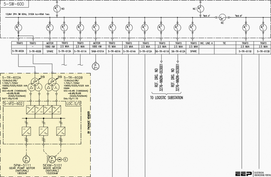
An example is given in Figure 3 that illustrates the main components normally used in the single-line diagram for motor installation applications. Another example is in Figure 4 gives the most common motor starters: direct-on-line (DOL), stardelta, and soft starter.
Also, the variable frequency drive controller is shown.
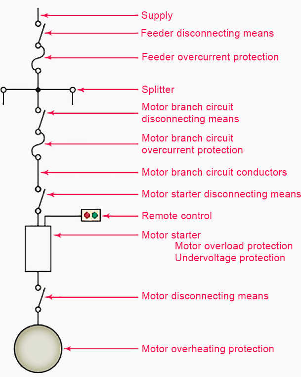
Additionally, the primary protective means, motor size, and voltage rating are all given in the single-line diagram. Note that the figure is only a sample that combines almost all components that can be seen in a single-line diagram. It is not necessary to have them all in one application.
Also, it shows disconnecting means, protective elements, a communication port, a motor starter, and a motor thermal protection element.
1.2 Wiring Diagram
A wiring diagram shows the point-to-point wiring between components and sometimes their actual physical configurations. Normally, it includes wire identification numbers for each conductor in the ladder diagram and sometimes color coding is used instead.
All MCCs components like coils, contactors, and motors are depicted in their actual positions in the installment. Indeed, a wiring diagram is essential for wiring devices and troubleshooting, but it is not that helpful when it comes to following the sequence of operation of a given circuit.
These circuits should be identified before proceeding with the analysis. These basic circuits are as per the following:
- Is the control circuit at the same voltage level of the power circuit? Is there a control power transformer?
- Is the control wiring of two-wire or three-wire?
- Is reverse starter needed?
A typical wiring motor starter is in Figure 5, where open terminals (marked by circles) and arrows represent the connections that need to be done by users. Two main circuits govern the start and operation of MCCS: the power circuit and the control circuit.
Electricity passes through starter contacts, overload relays, and to the motor in a typical starter wiring, which is a DOL starter, portrayed in Figure 6. Note that thick lines represent the power circuit, while the thin lines represent the control circuits.
Also, note the number of markings of the start and stop pushbuttons and their corresponding same numbering system in the circuit. Sometimes there is no line drawn from the control devices to the circuit due to complexity, so the numbering system is important.
The control circuit, on the other hand, is the one that energizes the main contacts through the developed electromagnetic field across the magnet coil of the starter that pulls the power contacts closed.
Keep in mind that the contacts, switches, and pushbuttons status follows the so-called “off-the-shelf” concept, which means the status of the contact reflects their conditions when power is not applied.
Hence, normally-open (NO) or normally closed (NC) in drawings refers to the “off-the-shelf” state.
1.2.1 Common/Separate Control Circuit Voltage Supply
The control circuit is separated from the motor circuit. These two circuits might not be at the same voltage level, so the circuit is referred to as a common control; otherwise, it is referred to as a separate control. The separate control scheme is implemented using two approaches, one of which is to run different wires from different voltage sources.
Alternatively, a control power transformer (CPT), also called a “control circuit transformer”, is used to supply the control circuit from the power circuit voltage source.
The common control scheme is shown in Figure 6, while the separate control scheme is depicted in Figure 7.
1.2.2 Two-Wire/Three-Wire Control
The control circuit wiring has two general categories:
- a two-wire control circuit (low voltage release) and
- a three-wire control circuit (low voltage protection).
The low voltage release circuit utilizes a maintained contact type of the available pilot devices, like a thermostat, a pressure switch, or otherwise. If the pilot device maintained contact is closed, the starter coil gets energized, thereby connecting the motor to the power circuit. When the pilot device contact is open, the coil is de-energized, which in turn drops off the motor connection.
Related electrical guides & articles


Salem Alshahrani
Electrical engineer (BEE & Meng). Specialized in substation design, especially in LV/MV switchgears and transformers. Passionate in power system planning, analysis, and stability studies.Profile: Salem Alshahrani
