
Estimated Study Time: 46 minutes
Circuit breaker switching duty
Circuit breakers (CBs) do interrupt fault currents and close onto faults. Besides, they could be used as isolation devices like disconnectors. The CBs manufacturers’ brochures and standards provide extensive data to select and assess the CBs performance, but designers must possess a reasonable knowledge of various breakers’ principles of operation so as to match a breaker to a specific application.
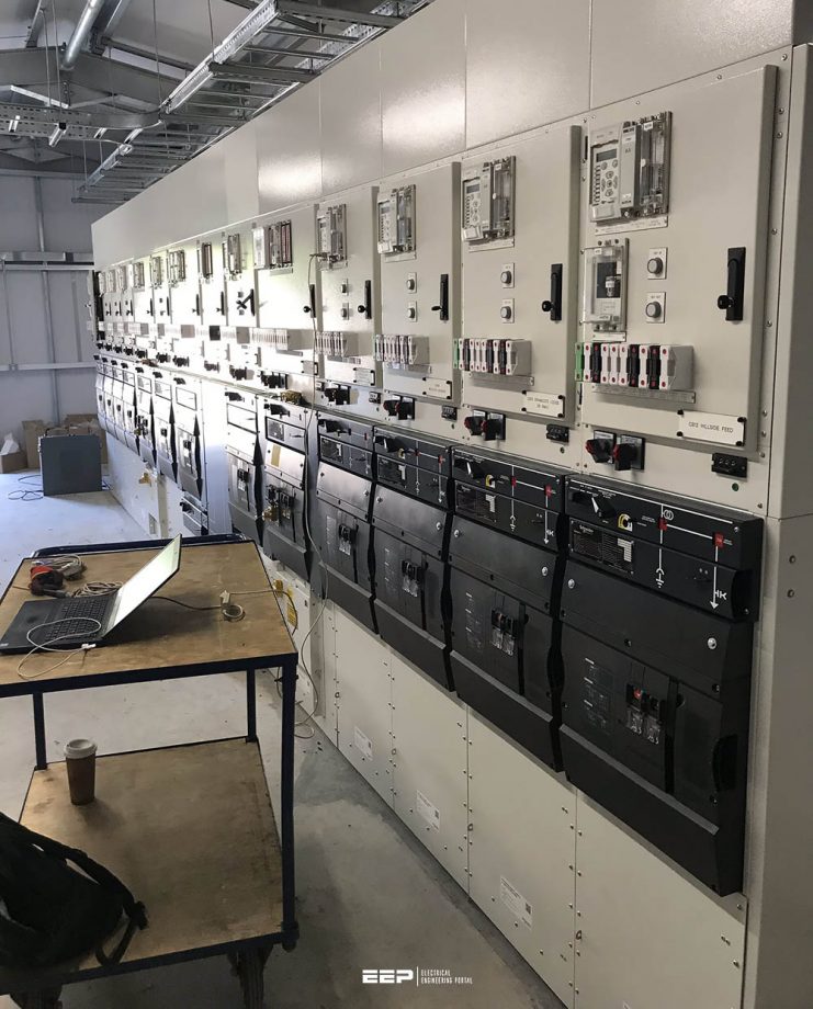 MV/HV switchgear (circuit breaker) switching capability and suitability for specific applications (photo credit: NSS Ltd.)
Moreover, substation modification and upgrading urge designers to have the know-how of different CBs characteristics. Opening and closing velocities, as well as stroke, or travel distance are the most important characteristics of a circuit breaker. They are dictated primarily by the requirement imposed by contacts. Opening and closing velocities are important to the contacts in order to avoid both contact erosion and contact welding.
CB stroke is primarily related to the ability of the circuit breaker to withstand the required operating dielectric stresses, which, in turn, is directly related to the total contact gap and the rate at which this gap increases.
The operating characteristics need to be specified for each mechanism along with the circuit breaker as per IEC 62271-100.
A list of breaker standards and basic performance requirements are presented first to lay the ground for the main topic. The breaker classification according to the media and the common breaker types in several voltage levels is discussed. The switching capability plays an important role in the breaker selection, so it is addressed thoroughly.
The overvoltage conditions experienced in breakers are elaborated since they are the driving factor for the switching capability. Then, different applications that entail special breaker types are put into discussion and related to some standards.
- MV/HV Circuit Breaker Standard
- Basic Performance Requirements for MV & HV Circuit Breakers
- Circuit Breaker Types:
- Common Breaker Types in MV, HV, and EHV
- Circuit Breakers Switching frequency and endurance classes
- Overvoltage Phenomenon
- Circuit Breaker Application:
1. MV/HV Circuit Breaker Standard
Standard design and performance requirements for HV and EHV CBs are given in the American standard IEEE C37 series and the international standard IEC 60056 [S10]. The IEEE C37 series comprises, among others, the following documents considered to be of principal importance in the specification of CBs.
There are some differences between the two standards, but in recent years there has been an effort to harmonize them, and for industrial installations in North America, it is acceptable to use the ANSI standards only.
IEEE C37.04 [S4] gives definitions and outlines underlying assumptions and criteria on which breaker performance is based. For the actual numerical values of the performance requirements, the standard refers to other standards, mainly C37.06 [S5] and C37.09 [S6]. Among other definitions, this standard defines the meaning of rated short-circuit current, rated interrupting time, rated transient recovery voltage, etc., and defines the required elements of the breaker interrupting the performance.
ANSI C37.06 [S5] presents a series of tables giving the required design characteristics of the CBs. The tables are entitled “Recommended Ratings”, but all major manufacturers would comply with the recommendation.
IEEE C37.09 [S6] outlines the test procedures for production, duty cycle, and routine acceptance testing of CBs. It is for guidance in writing detailed technical specifications, and for engineers performing and witnessing acceptance tests.
IEEE C37.010 [S7] is not a standard but an application guide for the benefit of users. The guide elaborates on:
- CB ratings as affected by ambient temperature
- Emergency overload conditions
- Correct use of interrupting times
- Use of the E/X rating multipliers for high X/R ratios and tripping times shorter or longer than the standard range of tripping time for the breaker
ANSI/IEEE C37.011 [S8] is really a guide rather than a standard. It describes methods of calculating transient recovery voltage (TRV) and presents guidelines for parameters of different network components to be used in TRV calculations, whether done manually or by digital computers.
ANSI/IEEE C37.012 [S9] and C37.010 [S7] are also application guides for the calculation of inrush currents and TRVs of capacitor banks, cables, and long transmission lines.
Go back to the Contents Table ↑
2. Basic Performance Requirements for MV & HV Circuit Breakers
Several points shall be available upon selecting a CB to be effective in functioning as a tripping device. These points are as follows:
- Tripping highest symmetrical/asymmetrical power frequency fault current available at highest system voltage.
- Withstanding highest rate of rising of TRV upon interrupting a fault current range from few amperes up to maximum interrupting capability. Measures must be taken if anticipated TRV exceeds the breaker capability.
- Interrupting out-of-phase switching current, or blocked if it is beyond the breaker standard limitation.
- Withstanding electromechanical forces upon making on the highest fault current and latch itself closed.Withstanding across the open contact the highest power frequency, switching impulse, and lightning impulse overvoltages without flashover conditions. Overvoltage protection must be applied if the calculated overvoltage exceeds the breaker standard limits.
- Withstanding the power frequency and the switching & lightning impulse overvoltages specified in the relevant standards for the external insulation of live tank breakers and breaker bushings.
Normally, TRV is not a problem in industrial installment, but it could be for vacuum CBs.
Related electrical guides & articles


Salem Alshahrani
Electrical engineer (BEE & Meng). Specialized in substation design, especially in LV/MV switchgears and transformers. Passionate in power system planning, analysis, and stability studies.Profile: Salem Alshahrani
