
Estimated Study Time: 20 minutes
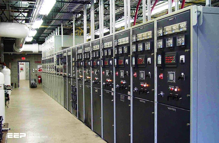
Power substations
Early consultation with the local Electricity Distributor is essential for agreement on a mutually approved MV/LV substation to act as the intake point for a particular site. This consultation is usually before detailed knowledge of the plant or project is known but it is essential that a fairly accurate load requirement be determined.
 MV/LV Power Substations Design and Schematics Notes (Network Supply & Enclosure Types)
Plant manufacturers must be approached to provide information relative to the equipment they are supplying and this, together with experience, enables a reasonably reliable load demand to be ascertained. Having this knowledge enables the rating of the power transformers and of associated switchgear to be decided.
All substations ought to be designed to be capable of extension unless it is obvious that such a facility will not be needed.The extent of such provisions must be weighed against the monetary outlay and be agreed as a viable proposition.
Standard equipment should be selected as far as possible to keep cost and delivery to reasonable levels. This equipment should comply with an appropriate standard (in the UK this would be a British standard).
Article is divided into two sections: the various network supply arrangements possible which determine the nature of the equipment utilised, and how this equipment is laid out and protected, i.e. the type of enclosure provided.
Contents:
- Medium voltage substations
- Low voltage substations
- Fault clearance
- Substation enclosures
- Substation cabling
1. Medium voltage substations
There are three common ways that an 11kV supply may be provided to a site: by a ring main, by duplicate feeders, or by a radial feeder or a single spur from a radial feeder.
The duplicate supply may be provided with either automatic or manual changeover facilities.
1.1 Substation with Ring-main unit
A ring-main unit consists of two manually operated incoming isolators and a tee-off circuit to an 11kV/400V/230V transformer. The tee-off may be controlled by a circuit-breaker or a fuse-switch, both providing a measure of protection to the transformer and acting as a back-up to the LV consumer’s network.
This is a very common arrangement.
Alternatively, a number of circuits may be established to supply motor starters at sites closer to the motors.
The main distribution board may also supply local general services such as lighting and small power directly in addition to circuits for more remote sub-distribution boards.
It is preferable to use motor control centres (MCCs) for process plant such as food or chemical manufacture where the production is automatically controlled. The cross connections between the monitoring equipment and the drive controller may be more readily effected.
Duplicate supplies may also be provided economically to the motor control panel.
Where the supplies are only for small power and lighting the main LV switchboard may be less elaborate with fuse-switches, MCCBs and fuse boards. Where splitter boards are used a 400V isolating switch is needed to enable fuses to be changed in safety.
This should be so interlocked that access to the fuses is not possible until the switch is open.
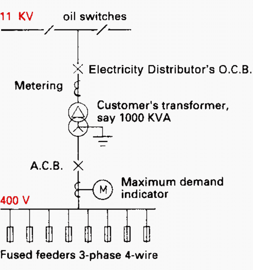
A typical ring-main unit is shown in Figure 1 above where the tee-off is controlled by a circuit-breaker and Figure 2 below where a fuse-switch is employed for this purpose.
1.2 Duplicate supply substation
A more elaborate and expensive design of substation is shown in Figure 3. This would provide firm power to a site where security of supply is important.
Interlocking ensures that only two out of the three circuit-breakers (i.e. controlling the supply cables and the bus-section switch) are closed at any one time. With this system each intake must be capable of providing the full load of the network.
1.3 Single-supply substation
Where a consumer is able to accept an interruption in supply there is no necessity to go to the expense of a duplicate feed, either from a ring-main unit or two separate cables.
A single cable supplying an 11kV switchboard can be used as shown in Figure 4, and this could well be the responsibility of the Electricity Distributor.
2. Low voltage substations
For loads up to about 300kVA the power is usually provided from the local supply authority’s network at 400V. As for MV substations, either single or duplicate feeds may be provided to the consumer’s main switchboard.
Quite often these boards are divided into sections, one supplying non-essential plant and the other essential equipment. In the event of a mains failure, the essential supplies can either be provided by a duplicate mains cable or more likely from a standby generator set.
There are a number of general points which are often overlooked in respect of substation design (like rating of circuits), which make it easier to understand the ratings commonly utilised.
A widespread site such as a dockyard or a large petrochemical plant may have a total load measured in megawatts. It is necessary therefore to have a number of substations.
Circuits supplying current-using equipment should not have a voltage drop exceeding 4.0% of the nominal voltage at the design current. However, it may be necessary to use a conductor larger than that required for the voltage drop to satisfy the motor starting conditions.
In addition the cables and protective gear must be designed to match the prospective fault current.
To size a cable therefore requires consideration of:
- Full load continuous rating
- Voltage drop under full load conditions
- Motor starting voltage drop
- Prospective fault current short time rating.
Each of these conditions is subject to additional constraints. For example, the full load rating must take into account the effect of a low voltage and a low power factor. These conditions will also apply to the voltage drop.
The fault current is obviously a function of the supply characteristics. It is wise to allow for some strengthening of the supply system as time passes.
3. Fault clearance
The circuit-breakers and fusegear must be able to clear faults before cables are overheated. They must also themselves be capable of accepting the mechanical, thermal and electrical stresses imposed by faults. Transformers, busbars, cable boxes and insulators must also be suitable for the fault level.
The contractor must ensure that he is installing fuses which are appropriate to the duty. A fuse failure may result in an explosion or the emission of flame.
It is particularly important to ensure that fuses in substations (which are subject to the highest fault levels on the system) have adequate short-circuit capacity and are fitted with the correct fuse link to protect the outgoing cables.
4. Substation enclosures
Substations may be either outdoor or indoor types or a combination of both. Site substations generally are no different from main substations, having the same equipment and layout but usually on a smaller scale.
All the same precautions have to be taken with respect to safety, access arrangements, protection, etc., as with main substations.
4.1 Outdoor substations
Where all the equipment is mounted in the open the enclosures must be of weatherproof design (i.e. suitable for all the relevant external influences). This generally relates to MV substations.
Ring-main units are used both indoors and outdoors and designs are available that are suitable for this. Distribution cabinets are needed for the LV distribution feeder cables.
Railings or anti-vandal fencing are provided to enclose the equipment to form the substation (Figure 5).
There are also packaged MV/LV substations that utilize standard indoor equipment mounted inside a weatherproof enclosure. The transformer may be outside
the housing which contains the MV and LV switchboards, separated by a corridor.
Room for rear access to the switchboards may have to be provided.
An economic arrangement of outdoor substations is the so-called integrated design which has switchgear mounted on the transformer cable boxes, permitting a
naturally cooled transformer to be employed (Figure 6).
4.2 Outdoor/indoor substations
The more conventional arrangement of MV substations is to have outdoor transformers with indoor 11kV and 400V switchboards.
Transformers are housed in an annexe to the switchroom and there may be separate chambers for 11kV and 400V switchboards, battery and charger and controls.
This arrangement is preferable for town or urban substations because of the convenience of using standard indoor switchgear rather than the more expensive weatherproof designs. The difference in cost between indoor and outdoor transformers is not great, and because of the need to provide adequate ventilation the trend is to install them outside with protection against vandalism.
A common practice for multi-transformer substations is to have weatherproof chambers for the MV and LV switchgear and metering and to mount the transformers in open pens as shown in Figure 7.
Where the MV switchgear is under different operational management from the LV side, the more conventional design of substation is probably the best. It is also much more flexible to cater for special protection, extensions, non-standard ratings or bulk-buying of components.
The chance of a mistake in connecting up is also reduced.
It ought to be noted that a number of materials such as steel, glass fibre and concrete are available to house the switchgear, metering and distribution equipment. Extensions are also available from some manufacturers.
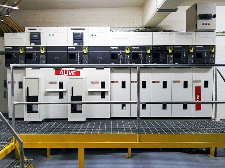
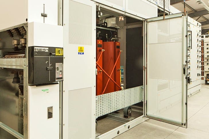
4.3 Indoor substations
Indoor substations require non-flammable equipment to make them safe or precautions to limit the fire risk. Basically there are two types of indoor substation.
The first comprises separate components such as switchgear, control and metering panels installed in a room(s). The disposition depends on the space available, size of equipment and importance of segregation.
The second, and becoming increasingly popular, is the packaged substation. This should not be confused with the outdoor package design which is quite different.
The MV switchgear may be integral with the unit but it is more likely that an 11kV cable will be brought from a nearby substation into the packaged substation.
A particular advantage of this form of MV/LV substation is that it can be located at the load centre of the area it is serving, even on the factory floor. It is extremely compact and, like the outdoor equivalent, requires the minimum of site work.
5. Substation cabling
Substation cabling may be run in trenches or ducts for outdoor substations or from overhead trays and cleats indoors.
An attractive alternative for the large indoor installation is a cable basement with trays supporting cables running directly below the equipment. Such an arrangement facilitates changes and additions at a later date if it is known that the factory or process may be subject to alteration.
It is also convenient if there is a separate control room because the control cabling then becomes significant so that it may be marshalled into reasonably large multicores for distribution to the associated controls, relays, interlocks and process plant.
For modest sized plants a cable trench is satisfactory. It is always true that where cables enter a building there are problems of preventing access of water and vermin.
A set of salt glazed ducts installed at a level of say 200mm above the floor of the trench prevents normal rain-water entering the building, particularly if they are sealed with a weak concrete mix of waterproof cement or some proprietary sealant such as Densoplast which is elastic enough to accommodate a modest relative movement of the cables.
Reference // Handbook of electrical installation practice by Geoffrey Stokes
Related electrical guides & articles


Edvard Csanyi
Hi, I'm an electrical engineer, programmer and founder of EEP - Electrical Engineering Portal. I worked twelve years at Schneider Electric in the position of technical support for low- and medium-voltage projects and the design of busbar trunking systems.I'm highly specialized in the design of LV/MV switchgear and low-voltage, high-power busbar trunking (<6300A) in substations, commercial buildings and industry facilities. I'm also a professional in AutoCAD programming.
Profile: Edvard Csanyi

i have learned a lot from all this technical articles you send to me i truly appreciate.
I WISH I CAN JOIN YOU……
Hi , my client requested from a ring mains, with RMU, we are providing a Genie Evo cubicles (500MM per section), questions:
1- How may 11kv HV cables will be entering the building (2 nos?)I suppose .
2-How many cubicles do we need for the Genie Evo? (3 Cubicles I suppose, one in, one to T off to the transformer and one out to the second 1iikv cable)
Many thanks
Hi please sent me your contacts detail cause i want a quotation on air breaker 1000amp, 4x 400 amp and 4x 200 amp breaker
Trafo merkezleri tasarımları için güzel bilgilendirme, teşekkürler alçak gerilimle ilgili makalelerinizide bekliyorum.
I wish to find out the standard design for low and high voltage substations and check if it is safe to have a process control room and offices on top of HV and LV substations. Please advise. Thank you, Jonathan Kavali, Process Engineer/Metallurgist, Papua New Guinea
I need mini sub-station with back up power to cater the school/university load
thanks for such informative articles for practicing engineers are quite useful.Much appreciate ,CS Nambisan