
Estimated Study Time: 18 minutes
Civil construction drawings
MV/LV substations are not only a point of supply but also provide a means of network isolation in the event of faults or emergencies. In that manner, a detailed substation information and layout drawings are required for civil engineers to prepare the civil construction drawings, such as plans for foundations, formwork and reinforcement, and building services.
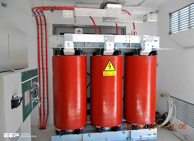 Preparing the civil drawings and construction of the MV/LV substation
The most important information required includes:
- Physical arrangement of equipment,
- Dimensions of equipment (distribution transformers, MV and LV switchgears, auxiliary supply panel, etc.),
- Normal building services,
- Gangways for transport, operation and servicing,
- Locations of cable and duct penetration in ceiling and walls,
- Loadings,
- Type of doors and windows (e.g., fire-resistant or fireproof) indicating how they open,
- Ventilation and air conditioning,
- Steel work and cable trenches required in the floor,
- Earthing for foundations and buildings,
- Lightning protection (if any), and
- Drainage.
Since all this information is pretty extensive, I will mention just some with a focus on the specific requirements regarding installation instructions and ventilation.
1. General About Indoor Installations
The design of buildings and rooms for electrical equipment must satisfy the operational requirements and other aspects as well.
These aspects include the following:
- Selected rooms are far from ground water and flooding.
- Easy access for operation, transport and firefighting services.
- Walls, ceilings and floors must be dry.
- In, over and under the rooms containing switchgear, the piping for liquids, steam and combustible gases should be avoided.
- Room dimensions must be appropriate to the nature, size and arrangement of equipment.
- The escape route from exit doors must not be longer than 40 m.
- Inside surfaces of switchgear room walls should be as smooth as possible to avoid dust deposits.
- The floor surface must be easy to clean, pressure-resistant, nonslip and water-resistant.
- Steps or sloping floor surfaces in switchgear rooms must be avoided in all circumstances.
- Windows can be easily opened or closed without personnel coming dangerously close to any live parts.
- Windows and doors must be secured.
- The rooms must be sufficiently ventilated to prevent condensation. Condensation and high relative humidity may lead to corrosion and reduced creepage distances.
In conventional switchgear installations, the arcing faults can create considerable pressure in the equipment room. Using pressure-relief vents can avoid any probable damage to walls and ceiling resulting from excessive high pressure.

2. Substation construction details
2.1 Substation Walls
All external substation walls should be of cavity wall construction. Cavity walls should be inner leaf 215 mm thick constructed from blocks conforming to EN 771-3, 7.5 N/mm2 laid flat, neatly pointed. External walls are usually finished to blend in with the surrounding buildings and applied that require no maintenance.
Internal walls between the customer’s property and the MV substation should be also 215 mm thick from blocks conforming also to EN 771-3.
2.2 Substation Floor and Ducts
A poured concrete floor is usually installed. The floor should incorporate a duct layout, oil trap and reinforcing steel. For electrical safety, reinforcing steel mesh should be incorporated into the substation floor. This is to ensure equipotential bonding between the floor slab and the electrical equipment.
Reinforcing steel mesh must be electrically isolated from all other steel in the building or building complex.

Walls and the base of duct should be constructed from poured concrete. The following are the critical dimensions:
- Height of rebate (~40 mm)
- Total width of duct plus rebate on either side should be ~530 mm
These dimensions are tightly specified because prefabricated duct covers are available from approved suppliers. These duct covers are factory cut to minimize amount of work on site.
2.3 Copper Earthwire Installation
Copper earthwires are laid below ground level and adjacent to the substation to provide a ‘substation main earth’. The design and layout of this ‘substation main earth’ are site specific and vary from one location to another depending on network configuration.
Earthwires are usually laid in conjunction with the main cable ducting.
Note that final ground-works, paving and landscaping should not be carried out until all the electrical cables and earthwires are installed.
2.4 Copper Earth Mat Installation
An approved copper earth mat must be installed under the front door step. The tail of the mat should run into the middle cable duct for connection to the main MV earth system. The mat is be installed 200 mm below the finished footpath level.
The wall must be core drilled at the correct level, or have a 50 mm duct installed at the construction stage to allow the earth mat copper tail to enter the central duct.

The best time to install the earth mat is when the final groundworks and footpath works are being carried out. Installing the step and the footpath too early could impede the cable installation.
The substation will not be energized if the earth mat is not installed to standard, confirmed by construction supervisor or by photograph.
Edvard Csanyi
Hi, I'm an electrical engineer, programmer and founder of EEP - Electrical Engineering Portal. I worked twelve years at Schneider Electric in the position of technical support for low- and medium-voltage projects and the design of busbar trunking systems.I'm highly specialized in the design of LV/MV switchgear and low-voltage, high-power busbar trunking (<6300A) in substations, commercial buildings and industry facilities. I'm also a professional in AutoCAD programming.
Profile: Edvard Csanyi
