
Estimated Study Time: 26 minutes
Transformer properties you MUST know
When selecting the type of transformer correctly electrical engineer needs to know its different electrical and thermal properties and the resistance to stresses due to faults or normal service of the transformer itself. This is crucial to know.
 MV/LV transformer protection against temperature rise, overloads, short-circuit & overvoltages
The transformer constructional technology thus finally also determines the selection of the adequate protection. Let’s talk about four most important aspects of MV/LV power transformer protection and how they are implemented.
- Protection against temperature rise
- Protection against overloads
- Protection against short-circuit
- Protection against overvoltages
1. Protection against temperature rise
During its normal operation a transformer has no-load losses and load losses which fundamentally translate into dispersed thermal energy. This energy depends on the construction of the transformer itself, its power and the installation conditions.
As the load increases consequently the losses and the room temperature increase favouring a more rapid degradation of the insulations and thus a greater probability of failure of the dielectric.
This situation could also occur when, with equal losses due to load, the room temperature and consequently the transformer temperature increase.
NOTE! The standards define insulation classes which indicate the maximum temperatures which can be reached by the transformers in their normal operation and which must not be exceeded.
Table 1 – Insulation classes
| Class | Transformer type | Average temperature rise limits, at rated current |
| Class B (130°C) | oil | 80°C |
| Class F (155°C) | resin | 100°C |
| Class H (180°C) | dry-type | 125°C |
Temperature rises depend not only on the load and the overcurrents which may be detected by the protection devices, but also on environmental factors (inefficiency of the cooling system, fault on the forced ventilation and increase of the room temperature) which influence the dispersal of heat produced by the transformer’s specific losses.
For this reason electronic temperature measuring devices are normally provided. These are necessary to give the alarm or to trigger transformer protection.
The following temperature sensors are available for most transformers: Pt100 thermosensors and PTC thermistors.
- PT100 – Supplies a signal proportional to the temperature monitored
- PTC – Supplies ON/OFF signal depending on whether the temperature measured is less or more than the sensor’s treshold
The sensors are positioned in the hot point of the winding. Both the PT100 and PTC signals must be processed by the temperature control unit, which does not form part of the standard equipment.
On request other accessories are available to check the temperature:
- A separate temperature display to be installed on the switchboard door
- An output relay for alarm, release and fans control
Table 2 – Typical transformer alarm and release temperature values
| Transformer type | Room (°C) | Alarm (°C) | Release (°C) |
| Oil | 40 | 105 | 118 |
| Resin | 40 | 140 | 155 |
| Air | 40 | 165 | 180 |
Table 3 – Temperature rise limits for cast resin transformers
| Transformer part | Insulating system temperature (°C) | Maximum temperature rises (°C) |
| Windings: (temperature rise measured with the heating element variation method) | 105 (A) | 60 |
| 120 (E) | 75 | |
| 130 (B) | 80 | |
| 155 (F) | 100 | |
| 180 (H) | 125 | |
| 200 | 135 | |
| 220 | 150 | |
| Core, metal parts and adjacent materials | – | In no case must the temperature reach values which would damage the core itself, other parts or adjacent materials. |
1.1 Ventilation of the transformers
As mentioned before, during its service a transformer produces heat due to losses. This heat must be dissipated from the room where the transformer is installed. For this purpose, one must ensure that there is adequate natural ventilation in the room.
If not, forced ventilation must be installed.
The CEI UNEL 21010 and equivalent IEC standards state that the temperature of the installation room air must not exceed the following values:
- 20°C average annual
- 30°C average daily
- 40°C maximum
The system protecting against temperature rises must be calibrated based on the maximum room temperature value of 40°C plus the maximum temperature rise determined by the standards and by the delta K of the hot point where the sensors are installed.
To evaluate the effectiveness of the natural ventilation and consequently check the section of the ventilation openings and the possible positioning heights, consider the following variables:
- TL = total losses in kW
- ΔT = temperature difference between air inlet and outlet
- Q = flow of air through the lower window in m3/sec
- H = distance in metres between the median of the cabin and the median of the upper window (outlet window).

We denote the net area of the lower air inlet window in m2 (excluding the grill) by S. Assuming ΔT = 15°C, the formula to dimension the inlet window is:
S = 0.185 × (TL × √H)
NOTE! – For different ΔT you should consult a manufacturer’s specialist.
The outlet window (S’) must be about 15% larger than the inlet window. If the air flow so calculated cannot be obtained, ventilation bars should be used.
If the transformer room is small, or badly ventilated, use forced ventilation. This is also necessary when the average annual temperature is higher than 20°C or when there are frequent transformer overloads.
To avoid affecting the natural convection in the room an air extractor may be installed in the upper opening, possibly controlled by a thermostat.

1.2 Checking the temperature
The temperature may be checked using Pt100 temperature sensors or thermometers. An alternative solution is to use PTC sensors, which however has the disadvantage that the temperature cannot be displayed. These systems are used to check the temperature of the lowvoltage windings.
For transformers that supply static current converters, the temperature of the magnetic core should also be checked.
1.3 Using PTC sensors
In three-phase transformers, the checking system is made up of three sensors, one per phase, connected in series. The sensors are just resistances which send the release signal to a relay when the reaction temperature threshold is exceeded.
When the protection relay is fed by the mains served by the transformer, a delayed contact inhibits the alarm and release signals from when the transformer is put into service until the relay coil is powered.
Where:
- Temperature sensors
- Protection relay
- Alarm or release
- Delayed contact
- Transformer terminal board
2. Protection against overloads
Overload is the phenomenon which occurs when the value of current absorbed by the system is higher than the rated value. The persistence of an overload inevitably leads to exceeding the acceptable temperature rise limits specified for the transformer, with the consequent risk of deterioration of the insulating materials.
This situation is sometimes preferable to an interruption of service (due to a temporary power peak) which could cause considerable material and economic damage.
In most cases the overloads are transient and thus generally do not affect the thermal equilibrium. The “acceptable” overload level is a function of the user’s need for service continuity and the type of system itself.

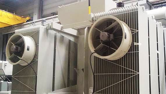
For insulating-liquid transformers the circulation of the cooling oil and the shape of the radiator containment tanks allow the rapid restoration of the insulation and the reduction of partial discharges, as well as allowing the transformer to reach its operating temperature quickly.
A partial solution of the problem may be the use of radial fans affixed to the cast resin transformers, allowing a temporary transformer overload up to 150% of the rated power.
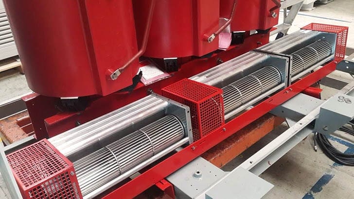
It should however be remembered that as the power increases the losses due to load increase. As they depend on the square of the current they can reach up to 2.25 times the rated value.
Axial fans should only be used in special and temporary cases to cool the windings or to have a sort of power reserve which may be used in emergency situations.
2.1 Overload in public distribution
In public distribution, in the short term priority is given to continuity of service. For this reason overloads do not generally lead to switching the transformer OFF.
Again for the same reason generally low-voltage circuits are always over-dimensioned and consequently an overload of the transformer never corresponds to an
overload of the conductors.
Attention should be paid however when the overloads repeat too frequently. In this situation the distributing organization should replace the transformer with a model of greater power.

2.2 Overload in industrial distribution
In an industrial installation, the overload can last for a short or long time. In these installations the main distribution board equipped with protective circuit breakers against overload and short-circuit is always immediately downstream of the transformers.
Management of the overload is in fact delegated to the circuit breakers on the low-voltage side which will detach the loads in an automatic or controlled way.

2.3 Overload in service distribution
In service installations, such as offices and shopping centres, continuity of service is fundamental. In these types of application conditions of regular
load which have starting regimes or similar behaviour rarely occur.
To guarantee maximum continuity of service even when there are overloads it is essential that the loads considered non-priority are managed and disconnected when needed by the transformer on the low-voltage side.

2.4 Protection against overloads by means of circuit breakers
For correct protection against overloads the current values absorbed by the system must not exceed a threshold between 110 and 150% of the rated current.
Protection against overload may be provided on both the medium-voltage side and the low-voltage side, depending on the transformer power. For low-power transformers the protection should be positioned on the low-voltage side, while for high-power transformers the protection should be provided on the medium-voltage side.
Protection against overloads on the MV side is provided using MV circuit breakers associated with maximum-current protections in constant time or independent time. These circuit breakers also guarantee protection against high fault currents.
LV-side protection is instead provided using LV circuit breakers installed in the main distribution board. These circuit breakers have an inverse time curve which protects the transformer. For correct transformer protection the circuit breaker is adjusted as a function of the rated current of the transformer upstream.
In this case remember that the fault current is lower (about 2 – 3 times the transformer In). These types of faults must not be underevaluated. Even if they are slight, if they are persistent, they could be extremely damaging for the transformer.
For suitable transformer protection against these faults circuit breakers with trips with the “thermal memory” function should be provided.
2.5 Protection against overloads by means of measuring the temperature
As previously stated, overload, is fundamentally associated to a temperature rise which is the real component to be kept under control, because its effects could lead to the rapid deterioration of the insulation materials and to the failure of the transformer’s dielectric properties.
Most cast resin transformers have these thermoresistors installed near the parts which are most critical from the thermal point of view.
For oil transformers instead the temperature measurement is managed using thermostats. The dielectric liquid works like a cooling fluid for the windings and tends to level the transformer internal temperature.
The use of a thermostat as measurement device allows managing more operation thresholds, which may be used for example to activate the load transfer or for forced cooling of the transformer.

3. Protection against short-circuit
The reference standards define that transformers must be designed and manufactured to withstand the thermal and mechanical effects due to external short-circuits without damage.
The impedance of the low-voltage circuits is the determining factor for calculating the short-circuit currents which could be damaging, from the point of view of electro-mechanical stresses, for a transformer with a fault immediately downstream.
A fault on the low-voltage side near the transformer terminals causes a thermal stress and a mechanical stress on the transformer itself which are functions of the values and duration of the fault.
Transformers are designed to withstand short-circuits between their terminals in the most critical situation which corresponds to having an infinite fault source and short-circuit.
For effective protection adequate protection devices should be provided on both the low-voltage side and the high-voltage side (taking account of any necessary selective coordinations).

3.1 Protection against short circuit with MV fuses
Because fuses are inexpensive and easy to use they are widely used to protect distribution transformers in public networks. While simplicity and price are definite advantages it is however true that there are limits in the use of fuses.
They are often used in conditions of low protection where special requirements of selective coordination or continuity of service are not required.
Fuses have a rated current value and a time/current melting property. MV fuses are generally available in 2 versions:
- Expulsion fuses and
- Limitation fuses.
The first are generally used in the air distribution system. The second are generally more widely used because of their capacity of response to high currents within a few milliseconds. The high response speed is the parameter which offers the capacity of limitation of the fuse itself and which allows adequate protection, even in the most serious conditions, reducing the risk of damage to the transformer and the associated circuits.
The choice of the most suitable fuse for protection reasons is however very complex and must take account of various factors.
The criteria for correct choice of a fuse are:
- The transformer service voltage
- The switch ON currents
- The transformer temporary overload level
- The time taken to remove the fault on LV side
- The selectivity level with the LV protections

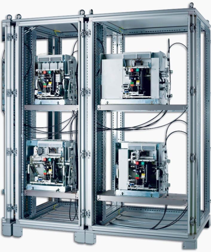
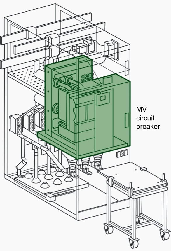
3.2 Protection against short circuit with MV circuit breaker
To obtain more effective protection, with adjustment levels of the current thresholds and the operating times and to obtain selectivity with respect to the protections placed downstream of the transformer on the LV side, high-voltage circuit breakers are more and more commonly used.
A protection circuit breaker dedicated to the MV transformer must have the following properties:
- Greater speed of operation of the MV protection device immediately upstream;
- Greatest possible speed for higher currents value of the short-circuit current on the LV side;
- They must let the switch ON current pass
- They must guarantee monitoring of the overload zone
4. Protection against overvoltages
Transformers may be affected by transient-induced overvoltages on the mains to which they are connected. These overvoltages, due to direct or indirect lightning strikes or to electrical operation on machines installed on the LV side, can in turn give rise to stresses on the transformer dielectric which could cause
its rapid ageing and consequent failure in time, giving rise to faults on the transformer.
The most critical conditions normally occur when voltage to the transformers is cut by non-automatic circuit breakers which interrupt the currents.
The risk of exposure to overvoltages is in the first instance linked to the place of installation and then to the following factors:
- Type of MV distribution network and type of LV network (above or under ground);
- Whether there are any overvoltage limitation devices (arresters or spark-gaps);
- Length and type of mains/transformer connection;
- Type of equipment connected and operation conditions;
- Quality of the earth and cabin connections.
Faults caused by overvoltages concern the insulation of the transformer and its components and may be divided into:
- Faults between the turns of the same winding (most frequent case);
- Faults between windings;
- Faults between the stressed winding and a touching conductor part (core or tank).
Spark-gaps and surge arresters (which perform much better) may be used to efficiently protect transformers against overvoltages.

Reference // Power balance and choice of power supply solutions by Legrand
Related electrical guides & articles


Edvard Csanyi
Hi, I'm an electrical engineer, programmer and founder of EEP - Electrical Engineering Portal. I worked twelve years at Schneider Electric in the position of technical support for low- and medium-voltage projects and the design of busbar trunking systems.I'm highly specialized in the design of LV/MV switchgear and low-voltage, high-power busbar trunking (<6300A) in substations, commercial buildings and industry facilities. I'm also a professional in AutoCAD programming.
Profile: Edvard Csanyi

Hello
I am working 6900/400Volt, 230KVA transformer, that is working under harmonics pollution caused by the absence of any filters on the circuit.I think that is the cause for one abnormal heat in the oil of the transformer ( 75ºC ). Its a Cooper Power Systems transformer class 65ºC. Considering the class of the transformer and a temperature environment of 26ºC, is it too high the temperature of 75ºC? Wich temperature can be considered high in this situation?
Thank you
What is the meaning of MV measuring cubicle ,Uo>trip
can I use multi core cable from transformer to LV panel instead of too many single core cables and what is the disadvantages
YES
Very useful helpful information to widen the knowledge on transformer maintenance.
As an electrical supervisor it helps me alot.
Thank you.
IT IS VERY GOOD SITE HOLDING VARIOUS ELECTRICAL TOPICS IN DETAILS AND RICH KNOWLEDGE FOR NEW COMERS OR JUNIORS TO TRAIN AND GAIN TO ENHANCE THEIR SKILLS IN THE FIELD OF ELECTRICAL FIELD.
PERSONALLY I HAVE MORE THAN 36 YEARS OF EXPERIENCE IN VARIOUS FERTILIZERS INDUSTRIES IN INDIA AND ABROAD, EVEN THOUGH I LIKE THIS SITE AND READ THE ARTICLES WHENEVER HAVE THE TIME SPECIALLY FOR TRANSFORMERS PROTECTION AND SUB STATIONS DESIGN PERTAINING TO HV / MV SYSTEMS.