
Estimated Study Time: 14 minutes
MV/LV Transformers, where everything starts…
The general term power supply in LV networks refers to the supply of electrical energy. The power supply, and more generally the different supplies, are provided by sources (mains supply, batteries, generator sets, etc.) which can be MV/LV transformers, diesel generator sets, and UPSs.
 MV/LV transformers - The most common power supply in low voltage networks
This technical article will explain the most common power supply for LV networks provided by an MV/LV transformer. Don’t be confused, the same transformer with or without some modifications can be used also as a backup power supply, special power supply for safety services, or auxiliary power supply.
Let’s see the most common power supply source – transformers that are used in MV/LV networks.
MV/LV transformers are generally divided into three types depending on their construction: Oil, Air-insulated and Resin insulated dry-type transformers.
- Oil transformers
- Air-insulated transformers
- Resin insulated dry-type transformers
- Medium-voltage winding
- Characteristics of MV/LV transformers
- Primary and Secondary Connection Configurations
1. Oil transformers
The magnetic circuit and the windings are immersed in a liquid dielectric that provides insulation and evacuates the heat losses of the transformer.
This liquid expands according to the load and the ambient temperature. PCBs and TCBs are now prohibited and mineral oil is generally used. It is flammable and requires protective measures against the risks of fire, explosion, and pollution.
Of the four types of immersed transformer:
- Free breathing transformers,
- Gas cushion transformers,
- Transformers with expansion tank and
- Transformers with integral filling, only the latter are currently installed.

Structural standards for immersed transformers
- Power from 50 to 2500 kVA (25 kVA possible):
- Primary voltage up to 36 kV
- Secondary voltage up to 1.1 kV
- Power > 2500 kVA:
- HV voltage greater than 36 kV
- IEC 60076-1, IEC 60076-2, IEC 60076-3, IEC 60076-4, IEC 60076-5
1.1 Free breathing transformers
A quantity of air enters the surface of the oil and the cover allows the liquid to expand with no risk of overflowing. The transformer “breathes”, but the humidity of the air mixes with the oil and the dielectric strength deteriorates.

1.2 Gas cushion transformers
The tank is sealed and a cushion of neutral gas compensates for the variation in volume of the dielectric (risk of leak).

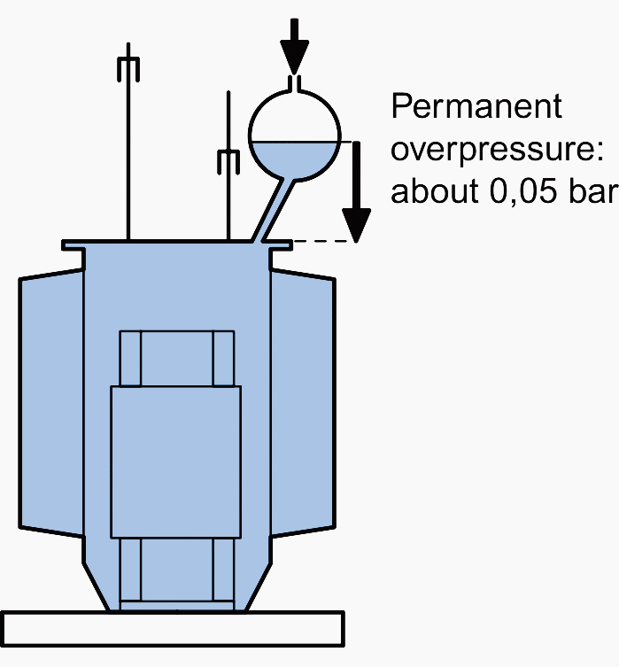
1.3 Transformers with expansion tank
To limit the previous disadvantages, an expansion tank limits the air/oil contact and absorbs the overpressure.
However the dielectric continues to oxidise and take in water. The addition of a desiccant breather limits this phenomenon but requires regular maintenance.
1.4 Transformers with integral filling
The tank is completely filled with liquid dielectric and hermetically sealed. There is no risk of oxidation of the oil.

The overpressure due to the expansion of the liquid is absorbed by the folds of the tank.
2. Air Insulated Transformers
The windings of air transformers are insulated by means of the wrapping of the windings themselves, the mounting of plastic partitions and compliance with adequate insulation distances.
A careful commissioning procedure must thus be followed, so as not to affect operation, such as the drying of the windings by means of heating elements installed on the transformer.

3. Cast Resin Transformers
Dry-type transformers, with one or more enclosed windings, are usually called cast resin transformers. These types, due to developments in construction techniques, are more and more widely used because of their reliability, their lower environmental impact compared to oil transformers, and because they reduce the risks of fire and spreading polluting substances in the environment.
Low-voltage windings are generally made of a single aluminium sheet, the same height as the coil, insulated by suitable material and heat treatment.
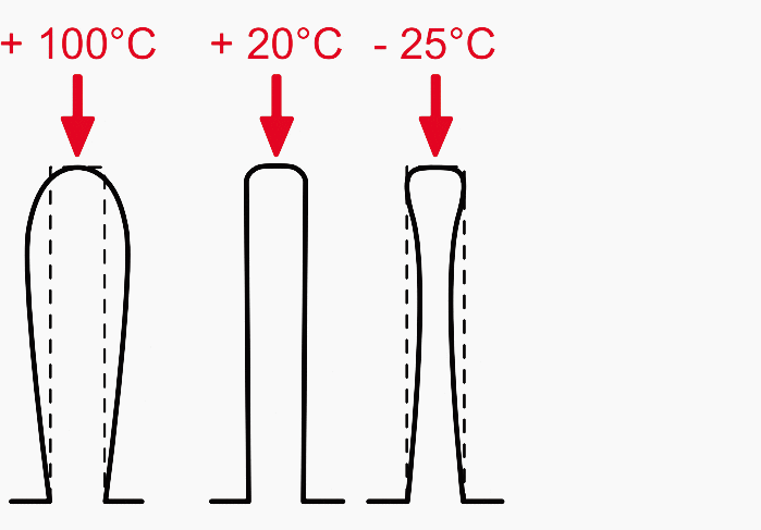
Cast resin transformers use class F 155°C insulating material, allowing for a maximum temperature rise of 100°K.

3.1 Applications
Cast resin transformers are used in a wide range of applications and represent the most reliable answer for distribution systems, power production, rectification, traction and for special requirements.
Distribution of electrical power
- Service sector: hospitals, banks, schools, shopping and cultural centres
- Infrastructures: airports, military installations, ports and off-shore installations
- Industry in general
Conversion and rectification
- Air conditioning systems
- Continuity units
- Railways, underground railways, tramways and cable cars
- Lifting and pumping systems
- Welding lines
- Induction furnaces
- Naval propulsion
Step-up transformers for power production
- Wind parks
- Photovoltaic systems
- Cogeneration systems
- Industrial applications
4. Medium-voltage winding
The technology used to make the MV windings of strips, rather than of wire, puts less stress on the insulation between the turns.
In windings made with strip conductors, each layer is made up of just one turn. If the voltage of a single turn of a winding is denoted by us, in strip windings the voltage between turns belonging to two adjacent layers is always us, while in traditional windings this voltage assumes the maximum value of (2n – 1) × us, as shown in the diagram below.
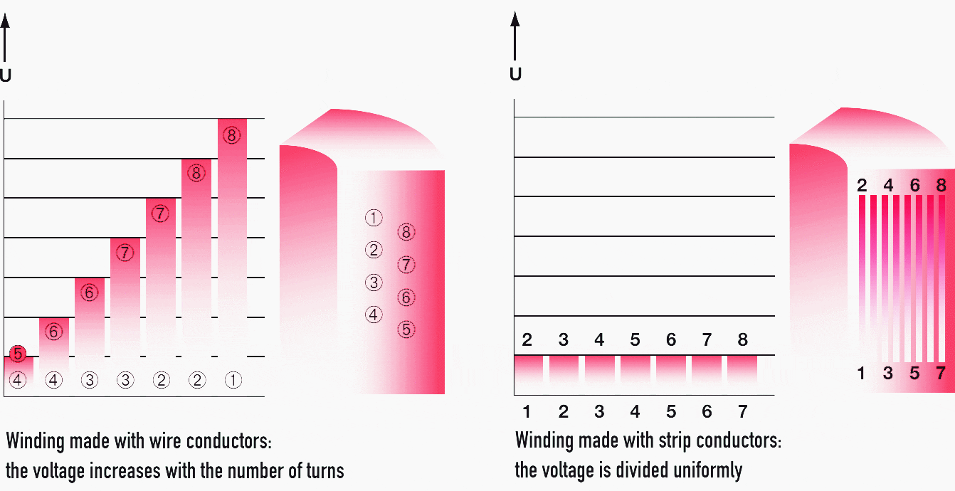
Transformers with strip windings thus have a greater resistance capacity to impulse voltages and at industrial frequencies, as well as a lower probability of occurrence of localised partial discharges. Strip winding also has the advantage of drastically reducing the axial forces due to short-circuit currents.
Division of the voltage between the turns of the medium-voltage winding.
5. Characteristics of MV/LV transformers
Table 1 – Standard characteristics

Table 2 – Characteristics connected with the construction method

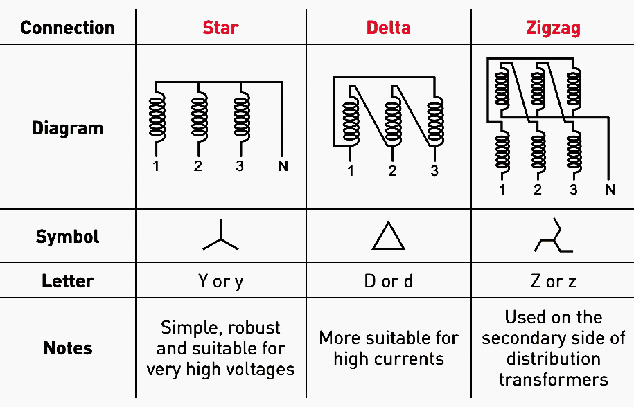
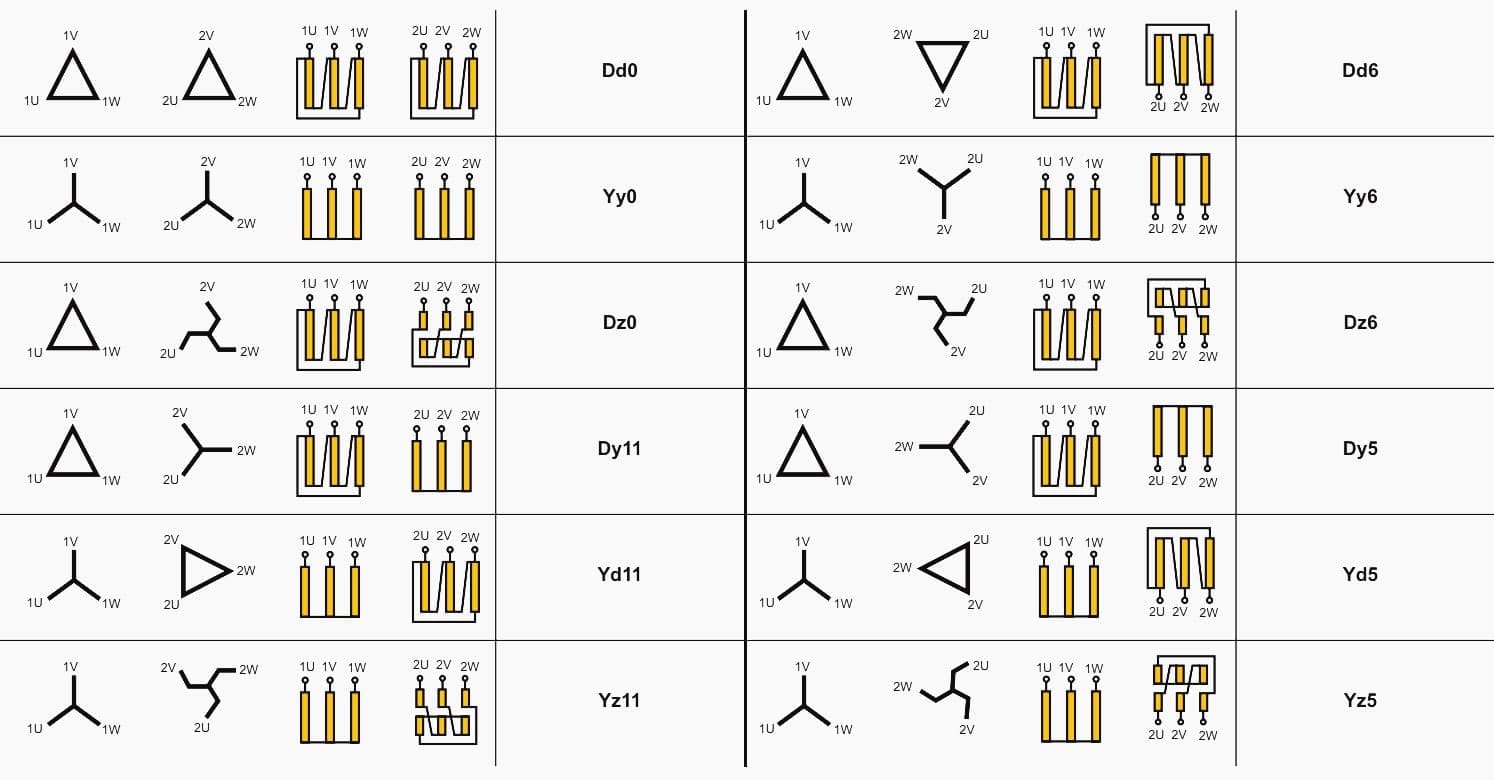
6. Primary and Secondary Connection Configurations
Symbols used to designate the connections. Internal windings may be connected in star, delta or zigzag configuration. Depending on the connection method the system of induced voltages on the low-voltage side is out of phase with respect to the average voltage by angles which are multiples of 30°.
The winding connection method is identified by 3 letters (upper case for the primary and lower case for the secondary):
- Y – star connection
- D – delta connection
- Z – zigzag connection

Associated with these letters are numbers which represent the phase shift, dividing it into 4 groups:
- Group 0 – no phase shift
- Group 11 – 330°
- Group 6 – 180°
- Group 5 – 150°
For this reason it is necessary to know the phase shift between primary and secondary phases. The table below shows the typical insertion diagrams.
Table 3 – Typical MV/LV transformer connection configurations
6.1 Time index
The designation of the connections (by letters) has an additional number that indicates the angular phase shift, for example Yy6, Yd11, Ynyn0 (external neutral).
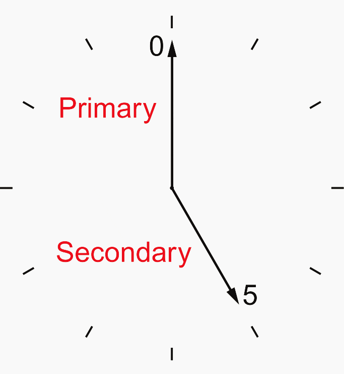
The voltage vector on the primary side is assumed to be located at midday. The time index indicates the position of the time at which the corresponding vector is located on the secondary side.
Example: Time index 5 (phase shift 150°)
6.2 MV/LV transformer common couplings
6.3 Coupling group
For two three-phase transformers to be able to operate in parallel, they must have:
- A ratio of their power < 2
- The same technical characteristics (transformation ratio)
- The same short-circuit characteristics (% of voltage)
- Compatible star or delta connections
- Identical time indices (terminal to terminal links) or belonging to the same coupling group if the operating state is balanced.
Parallel operation of transformers from different groups is possible by modifying connections, but they must be submitted for the approval of the manufacturer.

Source: Power balance and the choice of power supply solutions – Legrand
Related electrical guides & articles


Edvard Csanyi
Hi, I'm an electrical engineer, programmer and founder of EEP - Electrical Engineering Portal. I worked twelve years at Schneider Electric in the position of technical support for low- and medium-voltage projects and the design of busbar trunking systems.I'm highly specialized in the design of LV/MV switchgear and low-voltage, high-power busbar trunking (<6300A) in substations, commercial buildings and industry facilities. I'm also a professional in AutoCAD programming.
Profile: Edvard Csanyi

Estou sempre acompanhando suas postagens. Excelente trabalho.
Do you have any article about Buck-Boost Transformers?
Excelent information for electrotecnic !!
can I get PDF files for this.
Thank you for all the material.I love it.It helps me understand and learn more.I love the field.
Excellent reading.very beneficial to our young generation engineers and technicians.
The information are basic & comprehensive for Electrical Engineers to be kept in mind before entering in the field. This enable to approach the appropriate selection of MV/LV Transformers to it’s use. The application is equally imperative for senior network electrical engineers working with Utilities.
Document you share , are very useful to me thank u so much
Thanks for your efforts and helpful information.