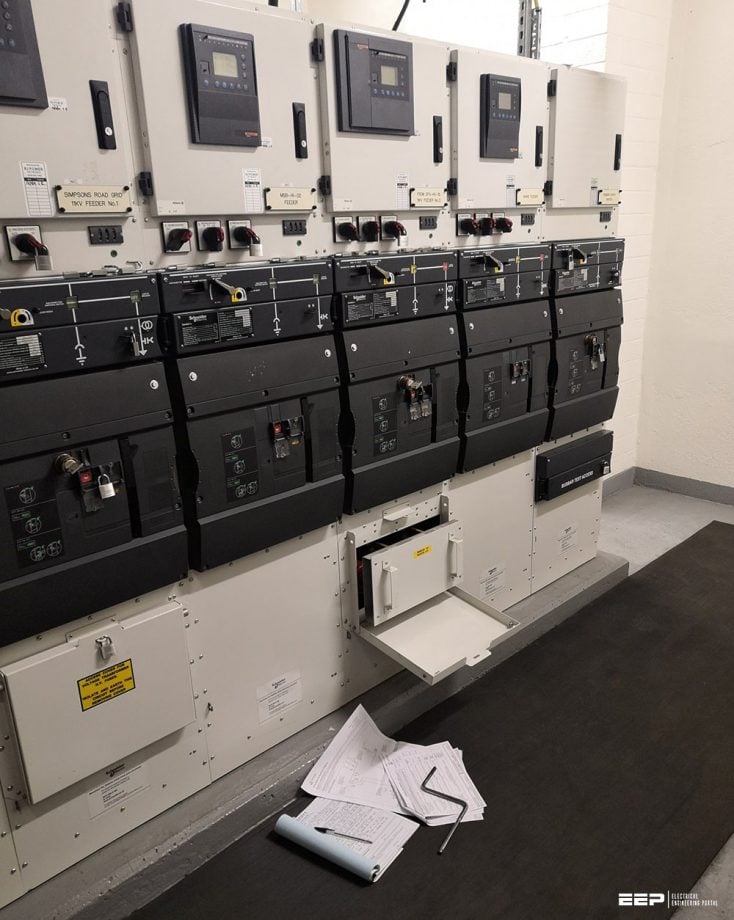
MV ring-main systems
Power systems are constructed can be operated as radial systems, ring-main systems or meshed systems. This technical article deals with nine most common topologies of ring-main systems, their characteristics and applications. Ring-main systems are common in the medium voltage range.

A large variety of ring-main systems are in operation with respect to permissible loading of the lines, reserve capability against outages, different arrangement of the feeding station and supply reliability.
Let’s discuss about characteristics of nine main topologies ring-main systems:
- Ring-Main System – Simple Topology
- Ring-Main System with Remote Station (Without Supply)
- Ring-Main System with Reserve Line
- Ring-Main System with Feeding Remote Station
- Ring-Main System as Tuple System
- Ring-Main System with Cross-Link
- Ring-Main System with Base Station
- Special-Spare Cable System
- Double-T Connection
1. Ring-Main System – Simple Topology
The simplest kind of ring-main system is obtained by connecting the line ends (starting from the radial system topology) back to the feeding station as outlined in Figure 1.
Usually ring-main systems are operated with open disconnection points (load disconnecting switch) at defned locations on each line, which provides for simple operation including a switchable reserve capability, depending on the loading of the lines.


The loading of the lines must be selected in such a way that in case of failure of a line the total load of this line concerned can be supplied after closing the load-switch at the open disconnection point.
The system is characterized by:
- Clear and simple structure.
- Moderate planning expenditure.
- Simple operation (similar to radial system) under normal operating conditions.
- Loading of lines during normal operation 50% of the permissible loading, higher loading possible depending on load duration.
- Reserve for outage of each line section given by the line itself.
- Investment cost not very high; reduction possible, if circuit-breakers are omitted. In this case one circuit-breaker has to be installed on the secondary side of the feeding transformer.
- Maintenance cost rather low.
- System losses can be minimized by changing the location of the open disconnection point.
- Voltage profile can be optimized, differences between feeding and receiving end of the lines depend on the location of the open disconnection point.
- Flexibility to respond to changing load conditions.
- Reserve for outage of feeding transformer or bus section usually available if an arrangement is selected as in Figure 1b.
- Standardization of cross-sections of the lines is given (usually only one cross-section shall be used).
- Feeder protection can be realized with overcurrent protection.
- Application in medium-voltage systems up to 35 kV, in case of high load density, in principle also in low-voltage systems.
Premium Membership Required
This technical article/guide requires a Premium Membership. You can choose an annually based Plus, Pro, or Enterprise membership plan. Subscribe and enjoy studying specialized technical articles, online video courses, electrical engineering guides, and papers. With EEP’s premium membership, you get additional essence that enhances your knowledge and experience in low- medium- and high-voltage engineering fields.
Check out each plan’s benefits and choose the membership plan that works best for you or your organization.


