
Estimated Study Time: 24 minutes
Negative Sequence Currents
As you know, generators and motors are supposed to operate with balanced three-phase loading, but exposure to unbalanced currents is inevitable. Unbalances could arise from many different sources like unbalanced loads, untransposed transmission line construction, faults and open phases, etc.
 What is negative sequence current and how does it affect generator work
These unbalances appear as negative sequence current in the generator leads. By definition, negative-sequence quantities have a rotation opposite that of the power system. This reversed rotating stator current induces double frequency currents in rotor structures.
The resulting heating can damage the rotor very quickly.
Potentially damaging low-current conditions such as an open phase or restricted fault were undetectable.
With the advent of solid-state and microprocessor technology, relaying is now available to provide generator protection over a full range of unbalance conditions.
- So, what is negative sequence current?
- Effects of negative-sequence current
- Sources of Negative Sequence Current:
- BONUS (PDF) 🔗 Download Guide to Protection of Synchronous Generators
1. So, what is negative sequence current?
The concept of negative-sequence current is rooted in symmetrical component methodology. The basic theory of symmetrical components is that phase currents and voltages in a three-phase power system can be represented by three single-phase components.
These are positive-, negative- and zero-sequence components. The positive sequence component of current or voltage has the same rotation as the power system. This component represents balanced load.
If the generator phase currents are equal and displaced by exactly 120°, only positive-sequence current will exist. A current or voltage unbalance between phases in magnitude or phase angle gives rise to negative and zero-sequence components.
Figure 1 – Symmetrical components: positive-, negative- and zero-sequence

The negative sequence component has a rotation opposite that of the power system. The zero-sequence component represents an unbalance that causes current flow in the neutral.
The negative sequence component is similar to the positive sequence system, except that the resulting reaction field rotates in the opposite direction to the d.c. field system. Hence, a flux is produced which cuts the rotor at twice the rotational velocity, thereby inducing double frequency currents in the field system and in the rotor body.
The resulting eddy currents are very large and cause severe heating of the rotor.
So severe is this effect that a single-phase load equal to the normal three-phase rated current can quickly heat the rotor slot wedges to the softening point.
They may then be extruded under centrifugal force until they stand above the rotor surface, when it is possible that they may strike the stator core.
A generator is assigned a continuous negative sequence rating.
For turbo-generators this rating is low – standard values of 10% and 15% of the generator continuous rating have been adopted. The lower rating applies when the more intensive cooling techniques are applied, for example hydrogen-cooling with gas ducts in the rotor to facilitate direct cooling of the winding.
Using this approximation it is possible to express the heating by the law:
I22t = K
where:
- I2 = negative sequence component (per unit of maximum continuous rating)
- t = time (seconds)
- K = constant proportional to the thermal capacity of the generator rotor
For heating over a period of more than a few seconds, it is necessary to allow for the heat dissipated. From a combination of the continuous and short time ratings, the overall heating characteristic can be deduced to be:

where I2R is the negative phase sequence continuous rating in per unit of maximum continuous rating (MCR)
To illustrate the derivation of these components refer to the loading on the sample system generator shown in Figure 2.
Figure 2 – Generator unbalanced currents

The generator loading is unbalanced and therefore, negative- and/or zero-sequence current is present in addition to the positive-sequence current. The sequence currents can be resolved from the phase currents when magnitude and phase angle are known.
Mathematically, positive (I1), negative (I2) and zero (I0) sequence currents in a system with ABC rotation are defined as (Equation 1):

Substituting phase currents and angles from Figure 1 into Equation (1), the sequence currents are found to be:

The rated current for the sample system is 4370 A. The positive-sequence current is then 4108 A/4370 A = 0.94 pu and the negative-sequence current is 175 A/4370 A = 0.04 pu.
The sample system generator is connected to the delta winding of a Generator Step Up (GSU) transformer. With no neutral return path, zero-sequence current can not exist. The calculated zero-sequence current is a result of measurement errors and should be considered zero.
Video Lesson – Negative Sequence or Unbalance Protection
2. Effects of negative-sequence current
2.1 Rotor heating
Magnetic field in the air gap that rotates at synchronous (rotor) speed in the same direction as the rotor. Because the rotor and the positive sequence induced rotor magnetic field move at the same velocity and direction, the field maintains a fixed position with respect to the rotor and no current is induced into the rotor.
Unbalanced current produces negative sequence current, which in turn produces a reverse rotating field in the air gap. This magnetic field rotates at synchronous speed, but in a reverse direction to the rotor.
Portions of the resulting induced current path present high electrical resistance to the induced current. The result is rapid heating.
Damage due to loss of mechanical integrity or insulation failure can occur in seconds.
Watch Video – Generator negative sequence overload protection
2.1.1 Cylindrical Rotor Generators
A cylindrical rotor is constructed from a solid-steel forging with slots cut along its length. Each field coil requires two slots, one for each side of the coil winding. A slot may contain one or more coil windings.
The ridges between the slots are called teeth. Figure 3 illustrates the rotor configuration.
Figure 3[/highligt2] – Salient-pole rotor

Groves are machined into the sides of each tooth to allow wedges to be forced in along the full length of the slot. The wedges hold the field windings in the slots. In some machines, conducting strips are installed in the slots between the wedge and the field coil.
These strips are connected at the retaining rings to provide a low-resistance path for the induced currents. The loops formed by these strips are known as amortisseur windings.
The slot configurations of the wedge, field coil and the optional amortisseur winding are shown in Figure 4.
Figure 4 – Slots and wedges

At the ends of the rotor body, the retaining rings hold the ends of the field windings in place against centrifugal force. The retaining rings are usually shrink fit to the rotor body, but in older machines they can be free floating with random contact with the rotor body.
The induced 120 Hz currents flow in loops along the body of a cylindrical rotor, as shown in Figure 5. There are as many current loops in the rotor as there are stator poles.
When alternating current passes through a conductor, in this case the rotor body, current densities are not uniform.
Figure 5 – Rotor currents
The “skin effect” causes alternating current to migrate to the outer surface of the conductor. This tendency increases with frequency.
In a cylindrical rotor, the 120 Hz induced current occupies a cross-section extending from the surface to a depth no greater than 0.1 to 0.4 inches. This forces the induced current into the teeth and wedges at the rotor surface. The resulting high current density significantly increases rotor resistance for 120 Hz current over that for DC or 60 Hz current.
Higher resistance produces higher losses and more heat per amp for the 120 Hz current than for lower frequency current.
The negative sequence tolerance of a generator is dependent on good electrical contact being maintained between rotor structures. Low resistance minimizes heating and prevents arcing at contact points. Designers include many features to improve conductivity.
These include the addition of amortisseur windings in the rotor slots to form low-resistance paths across the rotor surface. The ends of the amortisseur windings are connected to the retaining rings to provide a low-resistance bridge from the slot to the ring.
Aluminum slot wedges can also be used to reduce resistance in this current path.
Silver-plated aluminum fingers can provide a low-resistance current path from the wedges to the retaining rings. The rotor surface at the location of the retaining ring’s shrink fit is often silver-coated to minimize resistance and heating at the junction.
Two types of rotor failures are associated with unbalanced current.
Overheating of the slot wedges will cause annealing and a shear failure against the force of material in the slots. The second failure would be the retaining ring. Excessive heating can cause a shrink fit retaining ring to lift free of the rotor body. This would pose two problems.
The retaining ring may not realign after it cools, reseating in a cocked position on the rotor body. Vibration would result.
Also, the loss of good electrical contact while floating would result in pitting and burning at points of intermittent or poor contact. Retaining rings that are designed to float will also experience arc damage at points of intermittent contact or poor conductivity.
The resulting localized high temperatures can embrittle areas of the ring and lead to cracking under the varied stress of repeated unit startup and shutdown.
The heating characteristics of various designs of generator are shown in Figure 6 below.
Figure 6 – Typical negative phase sequence current withstand of cylindrical rotor generators

2.1.2 Salient Pole Generators
Salient pole generators normally have amortisseur winding in the form of conductive bars spaced across the face of each rotor pole. The ends are brazed to form a low-resistance path on the pole face.
There are two basic types of amortisseurs: Non-connected amortisseur windings are isolated on each pole face. Connected amortisseurs have conducting bars that bridge between poles to interconnect the ends of all the amortisseurs groups at each pole.
However, amortisseurs’ current tends to flow in the outer bars and the induced current can cause stress damaging due to unequal expansion of the bars.
Figure 7 – Amortisseurs windings

If the amortisseurs are not connected between poles – A large portion of the current induced in these windings flows down the pole body into the dovetail that holds the pole to the rotor then back into the adjacent pole. The junction at the dovetail will afford resistance, thus producing heat that can damage insulation and the rotor structure.
If the amortisseurs are connected between poles – The dovetail current is sharply reduced, but high current will flow in the connection between poles.
Connecting the amortisseurs also has a current balancing effect on the pole face bars. Salient-pole machines with connected amortisseurs will have a higher negative sequence current capability than those without. The limiting components on the connected machines are often the bars that bridge the poles.
The large induced current flowing in these bars can cause sufficient heat to anneal the bar, resulting in mechanical failure under centrifugal force.
Figure 8 – Difference in salient pole rotor and round or cylindrical rotor
2.2 Pulsating torque
The negative-sequence current produces a reverse rotating magnetic field in the air gap. This field produces a shaft torque pulsation at twice line frequency. The magnitude of the torque is proportional to the per unit negative-sequence current in the stator. The pulsations are transmitted to the stator.
If the stator is spring mounted, the pulsation will be absorbed. Without spring mountings, the pulsation will be transmitted to the stator foundation, where they can be a design factor.
In general, problems associated with torque pulsation are secondary to rotor heating concerns.
Suggested Course – Generator Protection Course: Concepts, Applications and Relay Protection Schemes
Generator Protection Course: Concepts, Applications and Relay Protection Schemes
3. Sources of Negative Sequence Current
3.1 Unbalanced Faults
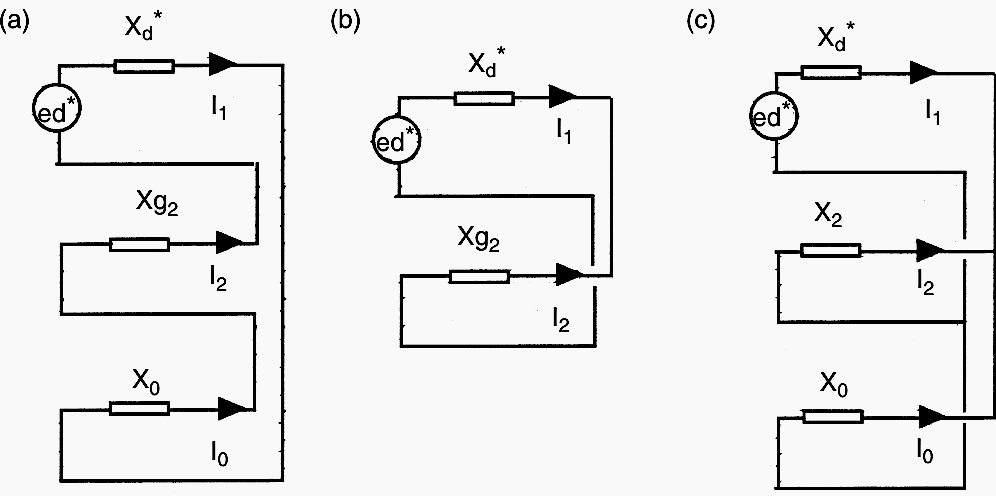
Unbalanced faults, encompassing phase-to-phase, phase-to-ground, or double-line-to-ground faults, generate substantial negative-sequence currents. Among these, the phase-to-phase fault is the most critical concerning negative-sequence current. The rationale for this is evident when analyzing the sequence diagrams for the three fault conditions.
See Figure 9.
The negative-sequence current produced by a ground fault is constrained by the positive, negative, and zero-sequence impedance. In a phase-to-phase fault, the negative-sequence current is only influenced by the positive- and negative-sequence impedance, resulting in a greater magnitude. The sequence connection of a two-phase-to-ground fault indicates that the zero and negative sequences are connected in parallel.
The comparative severity of the two-phase-to-ground fault vs the phase-to-ground fault is dependent upon the negative- and zero-sequence impedances.
A substantial grounding impedance significantly restricts the negative-sequence current during a ground fault. The ground impedance leads the negative sequence current in the generator during a double phase-to-ground fault to approximate that of a phase-to-phase fault.
Figure 9 – Sequence connections for unbalanced faults
3.2 Open Phase(s)
An open phase may occur because to a falling conductor or a malfunction of a breaker pole. In the previous instance, the condition is frequently associated with a problem detectable using standard relaying. In this instance, the condition may remain undiscovered by conventional line relaying. The generator’s performance is conditional upon its location of the open phase and the load intensity.
Should an open phase develop in the generator’s output pathway, specifically between the generator terminals and the high-voltage lead termination of the GSU transformer in the switchyard, while the generator operates at full load, hazardous negative-sequence current will be generated. Under identical load conditions, an open conductor on one of multiple interconnected transmission lines leading to a producing station’s high-voltage bus would produce negligible negative-sequence current at the generator.
In a site with numerous terminated network lines, an open phase on a line may induce negative-sequence current within the generator’s continuous capacity.
The investigation of the open phase condition will rely on symmetrical component methods. The integration of positive, negative, and zero-sequence networks to illustrate different fault states should now be well understood.
Figure 10 illustrates the connecting of the “A” phase, which is open on the high side of the GSU transformer. The synchronous impedance and EI are utilized in this model due to the minimal magnitude of negative-sequence current linked to an open phase. Relay operation durations exceeding 10 seconds are expected.
Due to this delay, the generator is presumed to be in a steady condition; therefore, Xd and EI are utilized in the computation.
Figure 10 – Open-phase representation by symmetrical components
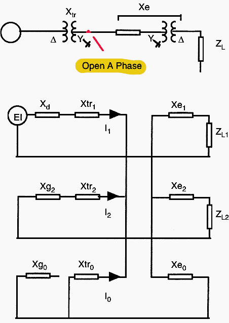
The grounding arrangement of the system significantly influences the generator’s negative-sequence current. The diagram depicts wye-grounded delta transformers for both local and remote buses. This connection will serve as a grounding point at both locations. In the absence of ground connections Xtr0 and Xe0, the zero-sequence impedance would be infinite, leaving the zero-sequence network open.
The positive-sequence current will not divide between the negative- and zero-sequence networks, resulting in an increased negative-sequence current in the generator.
It is important to notice that the load is presumed to be connected to the delta winding; hence, no zero-sequence current can circulate in the load. Consequently, the load impedance is excluded from the zero-sequence network.
These connections must be taken into account while developing the sequence diagram for alternative system setups.
Further Study – Synchronization and Reactive Power Control in Power System
4. BONUS (PDF): A Guide to Protection of Synchronous Generators
Download: Guide to Protection of Synchronous Generators (for premium members only):
Resources:
- Protective relaying for power generation systems by Donald Reimert
- Network protection and automation guide by Alstom
Related electrical guides & articles


Edvard Csanyi
Hi, I'm an electrical engineer, programmer and founder of EEP - Electrical Engineering Portal. I worked twelve years at Schneider Electric in the position of technical support for low- and medium-voltage projects and the design of busbar trunking systems.I'm highly specialized in the design of LV/MV switchgear and low-voltage, high-power busbar trunking (<6300A) in substations, commercial buildings and industry facilities. I'm also a professional in AutoCAD programming.
Profile: Edvard Csanyi

Thank for explaining the potential hazards to both machinery and personnel, the article emphasizes the importance of protecting motors from these adverse conditions. It’s a valuable resource for anyone looking to understand the critical role of negative sequence currents and the necessity of monitoring for phase imbalance in electrical systems.
This negative phase sequence practical face in my experience. 6 machines were operating in 220kv system. One machine was shutdown. While turbine trip. 2 phase pole failed to open and breaker failure protection failed to open all breaker. All machines received negative phase sequence alram. Protection engineers open all circuit breaker. Main interesting in this article about generator rotor found abnormal after removing the retaining rings. Thanks Qaiser Ali power generation 39 years. Again this article very informative same observations which in this article.
Very nice! It’s been a while since I’ve been through this.
Thank you.
Steve Hazlip P.E.
good article that explained the concept very well
A generator running with grid parallel, when load increases more then 40% of the generator capacity, generator tripped showing alarm ” current negative sequence ”
What’s the problem?
Is is due to loose power cable connection?
Very educational article.
I have a question:
I have two 500kVA 400V 50Hz generators to be synchronized and run in parallel as a standby system. If there is fault at the HV supply side (phase phase) that could trip HV breaker causing a interruption initiating a start-up of the standby system- Gen1 first and then Gen2. Could that in any way cause generator system fail to start-up due to phase sequence error, assuming the connected load to the downstream is balanced?
We had an experience that the generators did not start-up even after few attempts!
Can some one comment on this?
Start up of stand by unit should happen with CB in open condition. Is there any check Synch relay which give close command after verifying Check Synch condition.
First generator should close after it develops the volatge. But second gnerator should synchronize with first one.
This is a very educative piece. Thanks.
very practical write-up with insightful notes. Thumps up, Edvard!
Nice page, and nice to add some examples. But is there a mistake?
For the first phase, the given angle is -27.4 degrees, but in the calculations -24.4 degrees is used. (This confused me when I was checking my calculations…)
Yes. That seem to be one typo.
Besides, there is one more error in the phase angle of zero sequence component. Instead of 168.8 degrees, it should be -11.21degrees.
In any case, this lesson on asymmetrical components, negative sequence current and its effect on generators is superb! Congratulations and thank you, EEP!
My generator displays NEUTRAL PHASE SEQUENCE after the Breaker trips up. Whats the solution please.
A very good article on negative sequence current and its effect on generator. Though you give an example for the calculation of positive, negative and zero sequence currents from the unbalanced three phase load currents of a generator, I just wander if we can create a general equation for calculating the theory negative sequence impedance(resistance + reactance) of a generator (or motor) thus we can predict the negative sequence current at any situations of unbalanced three phase voltages. Please kindly comment and advise how to proceed for it.
A good article to under stand sequence Symmetrical /Assymetrical currents and their effect.
I appreciate the effort.
Good article. Thanks
I really appreciate your effort
A very nice article on Negative sequence current. Kudos for making it clear & simple.
Thanks for the article…
please clarify me that zero sequence current will present in a unbalanced system loads (no faults)…?
As the formula illustrates that we can have a value in Io even in unbalance load condition but many docs and articles saying zero sequence current will only present during earth related fault…
pls explain, whether I2 & Io both will be present during unbalance loads withou any faults related to ground?
@Manikandan : I hope u would have found the answer. If not, then this will be useful.
In an unbalanced 3 phase system, positive, negative & zero sequence impedance exists.
Remember, our Earth fault relays are set at 20% of Full Rated Load current to avoid tripping due to unbalance load current. In case of a line to ground fault, system draws an unbalance current and Earth fault relay trips after detecting zero sequence current above 20% Full Rated current.
A small correction in line no.2 :
In an unbalanced 3 phase system, positive, negative & zero sequence current exists.
Unbalance will cause negative sequence current to flow. If there is a ground path, it will also cause zero sequence current to flow.
For instance line to line fault causes negative sequence to flow. Line to line to ground causes negative and zero sequence currents to flow because of ground path. Hope it helps.
I believe I’ve found the discrepancy in calculation as per my previous comment, and it appears to be a typo in either the calculation or actual motor current. Your actual calculation is correct, however the calculated red phase angle slightly differs from the red phase angle mentioned in the initial motor currents (which I used).
The motor current stated a red phase angle being -27.4deg, but all the calculations start with -24.4deg for red phase.
This is the difference in our results.
Great info, thank you for the insight.
My calculations given the above values slightly differ, as below;
Positive is the same
Negative sequence current is correct, however the angle should be approx -35deg
Zero sequence current and angles should be 74.84 @ -116.497deg
Was having trouble with matching my symmetrical component calculations with yours, so I followed through my own results and all symmetrical components now added give the original value.
Really helpful Sir.., I have been working as Electrical Engineer in power plant sector..
Your website is amazing. I am an Electrical Engineering Student and I really enjoy reading your website. It gives me the insight into topics which are mentioned either not mentioned anywhere or mentioned in a compact way. Your elaborate discussions on topics like this helps clear the doubts that come into my way to fully understand a concept. I really appreciate and request you to keep on posting the updated content.
Very clear and simple article to understand negative sequence, thanks so much
Very good article. it helped me a lot to understand Negative Sequence current. In my Power Plant generator Negative sequence arises for very short time 10 to 20 mSec and then ends. is it fatal for the generator? Also this negative sequence current can also damage stator winding??Like flash stator winding??
Thanks for great Information :)
you are the Best!
This blog technical guide for utility. Thanks for sharing.
Very clear explanation!
thanks good topic.
with regards
P.samal
Thanks…
A great technical guide for utility… Especially to the designers and operators.
Perfect explanation CONGRATURATION
Now or Know? Could not read past that point.
Typo fixed, thank you.
Excellent technical article. Congratulations!
Julio Cesar Marques de LIma
Belo Horizonte – Brazil