
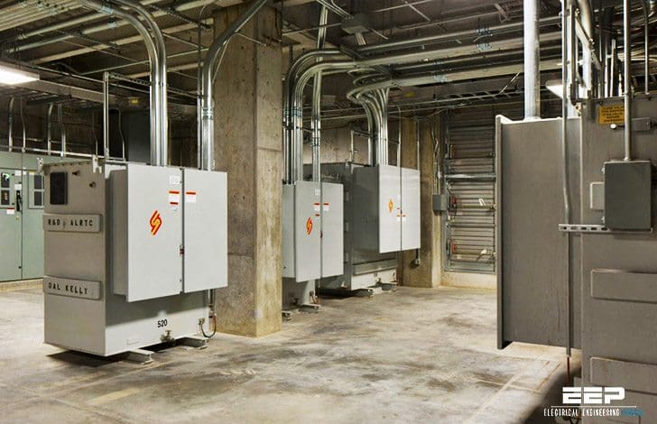
Housed in vaults
Network transformers, the distribution transformers that serve grid and spot networks, are large three-phase units.
Network units are normally vault-types or subway types, which are defined as (ANSI C57.12.40-1982):
- Vault-type transformers // Suitable for occasional submerged operation
- Subway-type transformers // Suitable for frequent or continuous sub-merged operation
Network transformers are often housed in vaults. Vaults are underground rooms accessed through manholes that house transformers and other equipment. Vaults may have sump pumps to remove water, air venting systems, and even forced-air circulation systems.
Utilities may also use dry-type units and units with less flammable insulating oils.

Technical Characteristics
A network transformer has a three-phase, primary-side switch that can open, close, or short the primary-side connection to ground. The standard secondary voltages are 216Y/125 V and 480Y/277 V. Table 1 below shows standard sizes.
Standard Network Transformer Sizes //
| Standard Ratings, kVA | |
| 216Y/125 V | 300, 500, 750, 1000 |
| 480Y/277 V | 500, 750, 1000, 1500, 2000, 2500 |
Transformers up to 1000 kVA have a 5% impedance; above 1000 kVA, 7% is standard.
X/R ratios are generally between 3 and 12. Lower impedance transformers (say 4%) have lower voltage drop and higher secondary fault currents. (Higher secondary fault currents help on a network to burn clear faults.) Lower impedance has a price though – higher circulating currents and less load balance between transformers.
Grounding connections //
Most network transformers are connected delta – grounded wye.
")
By blocking zero sequence, this connection keeps ground currents low on the primary cables. Then, we can use a very sensitive ground-fault relay on the substation breaker. Blocking zero sequence also reduces the current on cable neutrals and cable sheaths, including zero-sequence harmonics, mainly the third harmonic.
One disadvantage of this connection is with combination feeders – those that feed network loads as well as radial loads.
For a primary line-to-ground fault, the feeder breaker opens, but the network transformers will continue to backfeed the fault until all of the network protectors operate (and some may stick). Now, the network transformers backfeed the primary feeder as an ungrounded circuit.
An ungrounded circuit with a single line-to-ground fault on one phase causes a neutral shift that raises the line-to-neutral voltage on the unfaulted phases to line-to-line voltage. The non-network load connected phase-to-neutral is subjected to this overvoltage.
Some networks use grounded wye – grounded wye connections.
")
This connection fits better for combination feeders. For a primary line-to-ground fault, the feeder breaker opens. Backfeeds to the primary through the network still have a grounding reference with the wye – wye connection, so chances of overvoltages are limited.
Most network transformers are core type, either a three- or five-legged core. The three-legged core, either with a stacked or wound core, is suitable for a delta – grounded wye connection (but not a grounded wye – grounded wye connection because of tank heating). A five-legged core transformer is suitable for either connection type.
Reference // Electric Power Distribution Equipment and Systems – T.A.Short (Purchase from Amazon)


Looking for underground network transformer training. To include the distribution secondary system theory and operation, operation and maintenance of the network protector, and the theory and operation of the primary system.
great ..!
The problem of the wye-wye connection is the harmonics in the network, and for this reason this connection is never used in distribuition networks.
The wye-wye connection is only used in Hugh voltage, where the aim is to reduce the size of the insulation.
But to compensate the harmonics is necessary that the transformers have a third winding in delta connection.
Good presentation.
Does anybody has a information about acetyline gas in oil of new network transformers?
Good and simple presentation of Dist. Transformer and its S/Line diagrams.