
Estimated Study Time: 8 minutes
Injecting a harmonics with 6-pulse rectifier
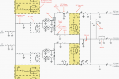
The diagram in figure 1 represents a simplified network comprising a 2,000 kVA six-pulse rectifier, injecting a harmonic current spectrum, and the following equipment which will be considered consecutively in three different calculations.
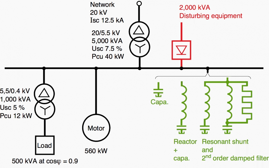 Figure 1 - Example of the analysis of a simplified network - Installation with disturbing equipment, capacitors and filters
So, let’s list these calculations and start with explanations:
- Single 1,000 kvar capacitor bank
- Anti-harmonic reactor-connected capacitor equipment rated 1,000 kvar
- Set of two filters
(comprising a resonant shunt tuned to the 5th harmonic and a 2nd order damped filter tuned to the 7th harmonic)
Note that:
- The 1,000 kvar compensation power is required to bring the power factor to a conventional value;
- The harmonic voltages already present on the 20 kV distribution network have been neglected for the sake of simplicity.
This example will be used to compare the performance of the three solutions. However the results can obviously not be applied directly to other cases.
1. Capacitor bank alone
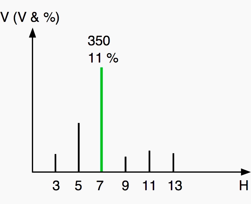
The network harmonic impedance curve (see fig. 2), seen from the node where the harmonic currents are injected, exhibits a maximum (anti-resonance) in the vicinity of the 7th current harmonic.
This results in an unacceptable individual harmonic voltage distortion of 11% for the 7th harmonic (see fig. 3).

The following characteristics are also unacceptable:
- A total harmonic voltage distortion of 12.8% for the 5.5 kV network, compared to the maximum permissible value of 5% (without considering the requirements of special equipment);
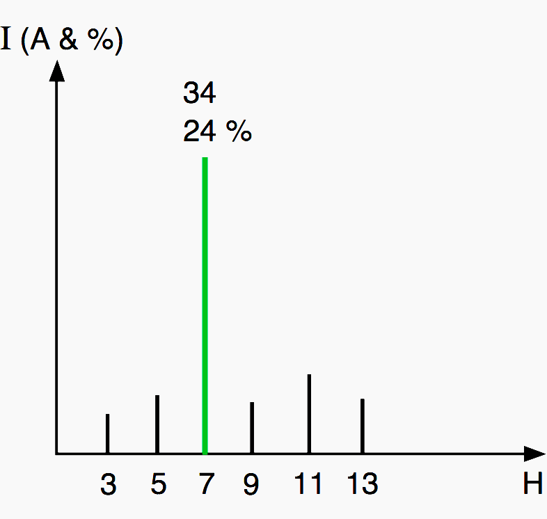
- A total capacitor load of 1.34 times the rms current rating, exceeding the permissible maximum of 1.3 (see fig. 4).

The solution with capacitors alone is therefore unacceptable.
2. Reactor-connected capacitor bank
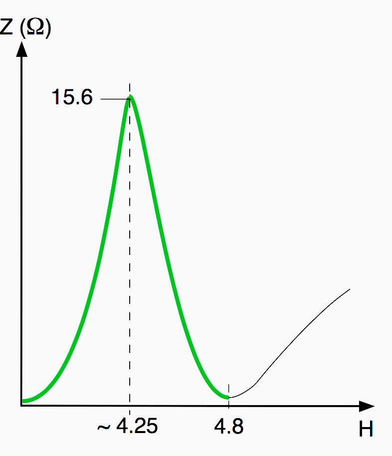
This equipment is arbitrarily tuned to 4.8 f1.
Harmonic impedance
The network harmonic impedance curve, seen from the node where the harmonic currents are injected, exhibits a maximum of 16 ohms (anti-resonance) in the vicinity of harmonic order 4.25. The low impedance, of an inductive character, of the 5th harmonic favours the filtering of the 5th harmonic quantities.
Voltage distorsion
For the 5.5 kV network, the individual harmonic voltage ratios of 1.58% (7th harmonic), 1.5% (11th harmonic) and 1.4% (13th harmonic) may be too high for certain sensitive loads. However in many cases the total harmonic voltage distortion of 2.63% is acceptable.
For the 20 kV network, the total harmonic distortion is only 0.35%, an acceptable value for the distribution utility.

Capacitor current load
The total rms current load of the capacitors, including the harmonic currents, is 1.06 times the current rating, i.e. less than the maximum of 1.3. This is the major advantage of reactor-connected capacitors compared to the first solution (capacitors alone).
3. Resonant shunt filter tuned to the 5th harmonic and a damped filter tuned to the 7th harmonic
In this example, the distribution of the reactive power between the two filters is such that the filtered 5th and 7th voltage harmonics have roughly the same value. In reality, this is not required.
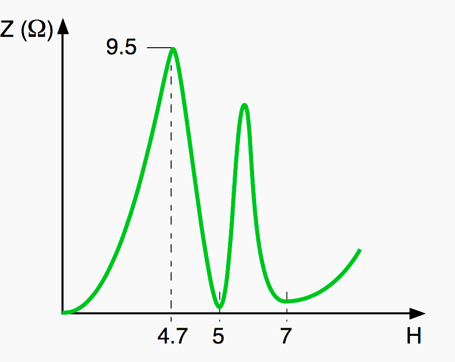
Harmonic impedance
The network harmonic impedance curve, seen from the node where the harmonic currents are injected, exhibits a maximum of 9.5 ohms (anti- resonance) in the vicinity of harmonic 4.7.
- For the 5th harmonic, this impedance is reduced to the reactor resistance, favouring the filtering of the 5th harmonic quantities.
- For the 7th harmonic, the low, purely resistive impedance of the damped filter also reduces the individual harmonic voltage.
- For harmonics higher than the tuning frequency, the damped filter impedance curve reduces the corresponding harmonic voltages.
This equipment therefore offers an improvement over the second solution (reactor-connected capacitors).
Voltage distorsion (see fig. 34 )
For the 5.5 kV network, the individual harmonic voltage ratios of 0.96%, 0.91%, 1.05% and 1% for the 5th, 7th, 11th and 13th harmonics respectively are acceptable for most sensitive loads. The total harmonic voltage distortion
is 1.96%.
For the 20 kV network, the total harmonic distortion (THD) is only 0.26%, an acceptable value for the distribution utility.

Capacitor current load
The capacitor rating must be adequately chosen considering the overvoltage at fundamental frequency, the harmonic voltages and currents. This example demonstrates an initial approach to the problem.
- The spectra of the currents flowing in the reactors connected to the capacitors;
- The total voltage distortion at the capacitor terminals;
- Reactor manufacturing tolerances and means for adjustment if necessary;
- The spectra of the currents flowing in the resistors of the damped filters and their total rms value;
- Voltage and energy transients affecting the filter elements during energization.
These more difficult calculations, requiring a solid understanding of both the network and the equipment, are used to determine all the electro- technical information required for the filter manufacturing specifications.
Reference // Harmonic disturbances in networks, and their treatment by C. Collombet, J.M. Lupin and J. Schonek (Schneider Electric)
Related electrical guides & articles


Edvard Csanyi
Hi, I'm an electrical engineer, programmer and founder of EEP - Electrical Engineering Portal. I worked twelve years at Schneider Electric in the position of technical support for low- and medium-voltage projects and the design of busbar trunking systems.I'm highly specialized in the design of LV/MV switchgear and low-voltage, high-power busbar trunking (<6300A) in substations, commercial buildings and industry facilities. I'm also a professional in AutoCAD programming.
Profile: Edvard Csanyi

I’m still learning or a student of the field. Is there a “cheat sheet” on harmonics and what each harmonic would do to the equipment or system?
Hello and best regards.
First of all thank you for sharing all technical fundamentals and Please provide technical information about 20 kV overhead power substation including:
Provide protection and switching systems for its oil transformer.
Thanks
First of all thank you for sharing all technical fundamentals but I want to know how to calculate Diesel Generator exhaust pipe, size fuel pipe size , and its tank capacity as well as I want to know how to calculate harmonics distortion In SLD 11kv / 433v substation.
Hi ,
I have a question. I am a solar electrician and at work the boss has installed two Feronius inverters to a 30 Kw solar system on a commercial premises. They are are kitchen manufacturer with three cnc machines with there own inverters. The company is now having electrical problems with there machines. Could this be a harmonic problem between the solar inverters and the machines own inverters.?
Regards
Mark
Mark – After installing Solar Inverters, it is expected that the site would face Electrical Failure or Harmonic Failure Problem. We have attended many such problems and you can see one such case study at the URL: http://enconengineers.in/solar-power-inverter-harmonic-filter/
As in the above Case Study and also in your case, the client did not face any electrical problem until they install the Solar Inverter. This is true, but it is also not true that the Solar Inverter alone is creating the trouble.
The Harmonic Problem depends on the Sum Total Load on the Power System. And also Sum Total Non-Linear-Loads in the Power System. That precisely the reason why your client is facing the problem after solar installation —- These problems are 100% solvable, as shown in the case study. The power and harmonic data are required for designing a solution.
This is direction ..eep..great stuff