
Estimated Study Time: 13 minutes
Ferroresonance and its causes
Due to the multitude of various sources of capacitances and non-linear inductances in a real power network and the wide range of operating conditions, configurations under which ferroresonance can occur are endless. Experience has, however, made it possible to list the main typical configurations that may lead to ferroresonance.
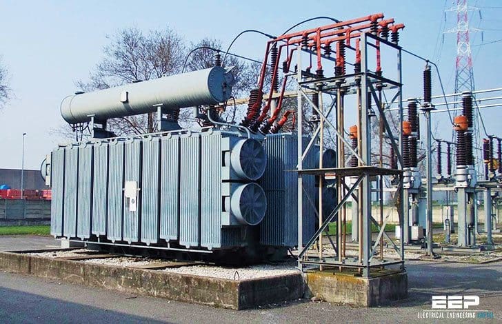 Six network operating conditions under which ferroresonance can occur (photo credit: geisrl.it)
A six most common examples are explained below:
- Voltage transformer energized through grading capacitance of one (or more) open CB(s)
- Voltage transformers (VT) connected to an isolated neutral system
- Transformer accidentally energized in only one or two phases
- Voltage transformers and HV/MV transformers with isolated neutral
- Power system earthed through a reactor
- Transformer supplied by a highly capacitive power system with low short-circuit power
1. Voltage transformer energized through grading capacitance of one (or more) open circuit-breaker(s)
In EHV, certain switching operations (padlocking a bus coupler or switched busbar circuit-breaker, removal of a fault on a busbar section…) can drive voltage transformers (VT) connected between phases and earth into ferroresonance.
These configurations can be illustrated by the circuit in figure 1. Opening of circuit breaker D initiates the phenomenon by causing capacitance C to discharge through the VT which is then driven into saturation. The source delivers enough energy through the circuit breaker grading capacitance Cd to maintain the oscillation.
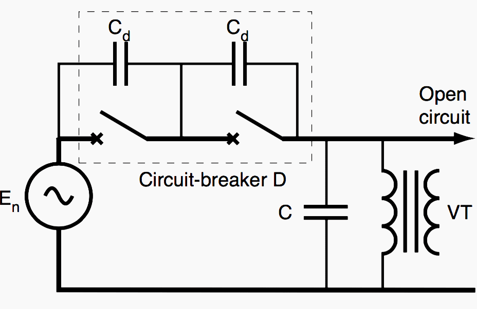
Capacitance C corresponds to all the capacitances to earth of the VT and the connection supplied by means of the grading capacitances of the open circuit-breaker(s).
Ferroresonance is of the subharmonic type.
2. Voltage transformers (VT) connected to an isolated neutral system
This earthing system can be chosen, can result from the coupling of an isolated neutral emergency source or from a loss of system earthing. Transient overvoltages or overcurrents due to switching operations on the power system (load rejection, fault-clearing etc.) or to an earth fault, can initiate the phenomenon by driving into saturation the iron core of one or two of the VTs of the parallel ferroresonant circuit in figure 6.
Ferroresonance is then observed both on the phase-to-earth voltages and on the neutral point voltage (VN).
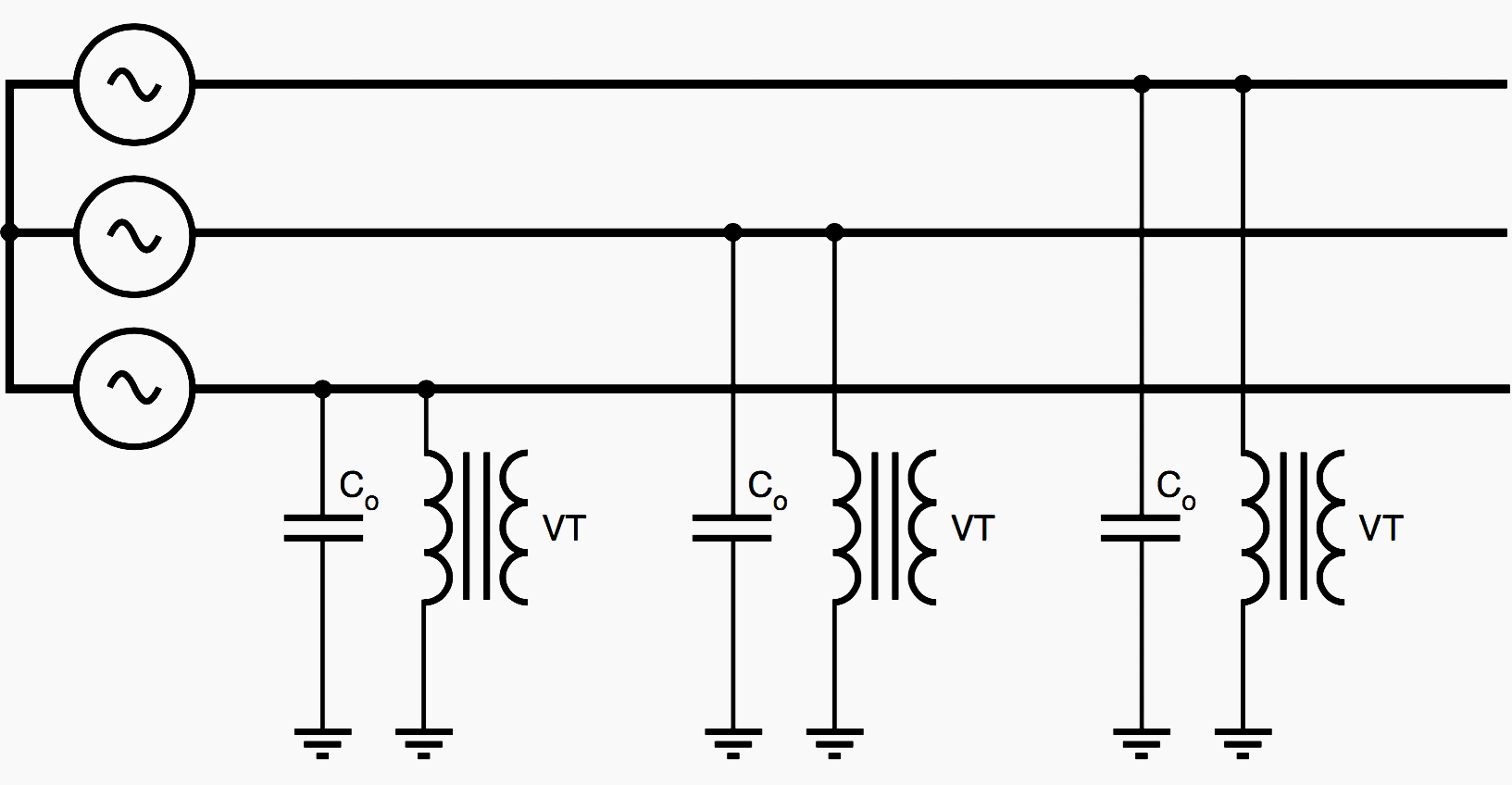
The neutral point is displaced and the potential of one or two phases rises with respect to earth, which may give the impression of a single phase-to-earth fault in the system.
Depending on the relative values of the magnetizing inductance of the VT and the capacitance C0, ferroresonance is fundamental, subharmonic or quasi-periodic.
3. Transformer accidentally energized in only one or two phases
A few examples of configurations at risk are given in figure 3 below. These configurations can occur when one or two of the source phases are lost while the transformer is unloaded or lightly loaded, as a result of a fuse blowing on an MV power system, of conductor rupture or of live works.
For example when commissioning a remote controlled breaking cubicle.
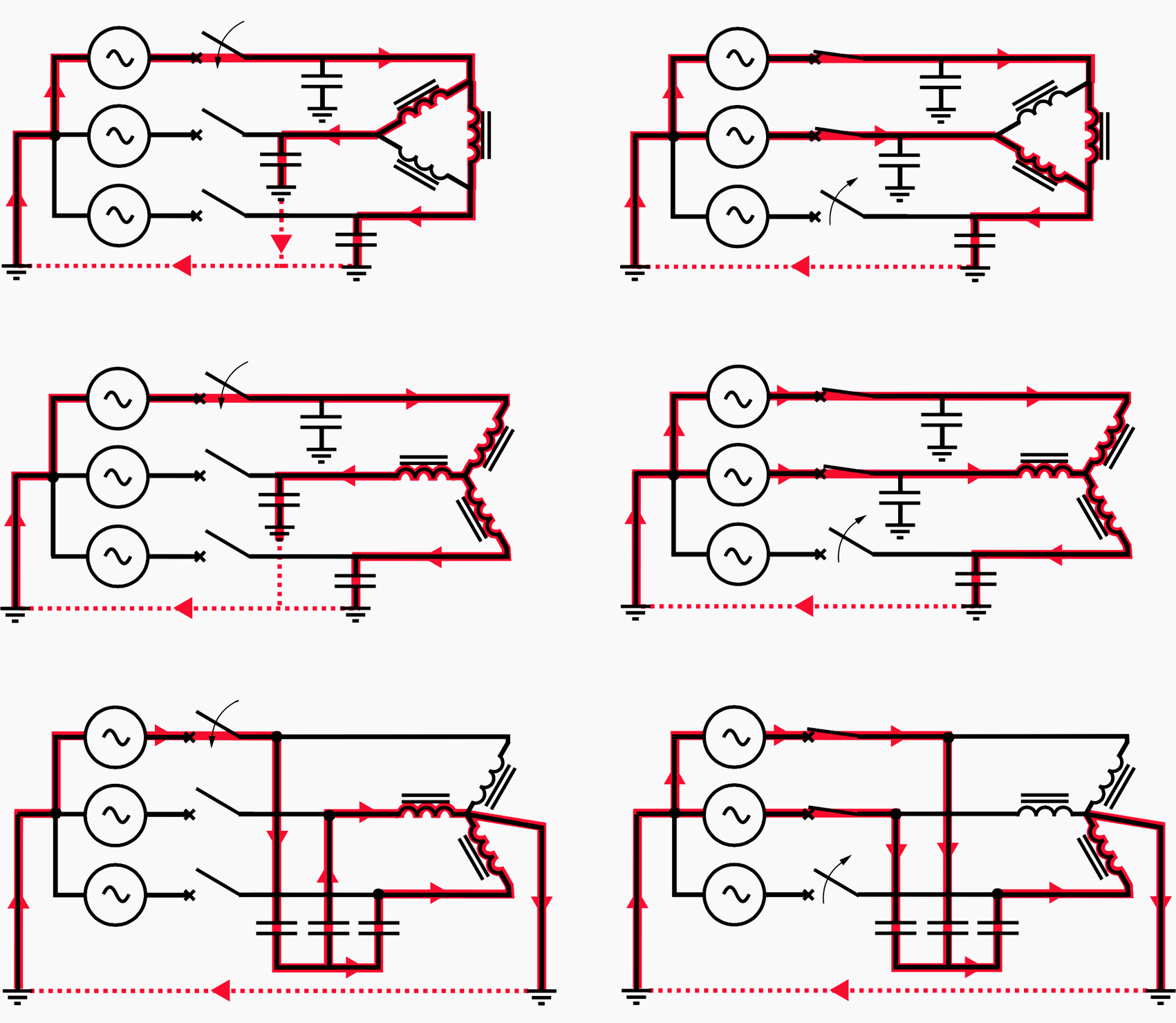
The capacitances can be in the form of capacitance of underground cable or an overhead line supplying a transformer whose primary windings are wye connected with isolated or earthed neutral, or delta connected.
For example the series ferroresonant circuit is made up of the connection in series of the phase to earth capacitance (between circuit breaker and transformer) of the open phase and the magnetizing impedance of the transformer. The modes are fundamental, subharmonic or chaotic.
The phase-to-phase and phase-to-earth capacitances, the primary and secondary windings connections, the core configuration (three single-phase, free flux or forced flux), the voltage source system neutral earthing (solidly earthed, earthed, isolated) and the supply mode (one or two phases energized) are all factors involved in the establishment of a given state. Isolated primary neutral is more susceptible to ferroresonance.
To avoid such risks, use of multi-pole breaking switchgear is recommended.
4. Voltage transformers and HV/MV transformers with isolated neutral
Ferroresonance may occur when the HV and MV neutrals are isolated, and unloaded VTs are connected on the MV side between phase and earth (see fig. 4a).
When an earth fault occurs on the HV side upstream from the substation transformer, the HV neutral rises to a high potential. By capacitive effect between the primary and secondary, overvoltages appear on the MV side, and may trigger ferroresonance of the circuit made up of the voltage source E0, the capacitances Ce and C0 and the magnetizing inductance of a VT (see fig. 4b ).
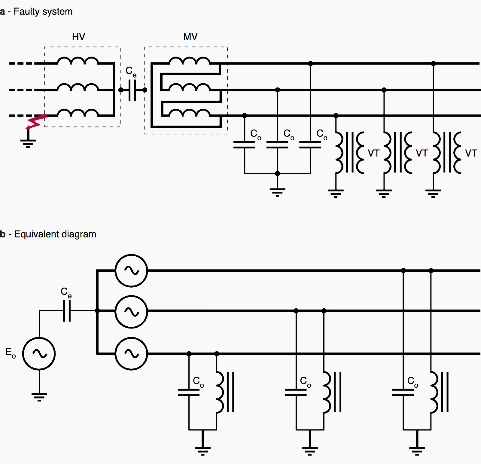
Where:
- E0 – zero-sequence voltage on the HV side
- Ce – capacitance between HV and MV winding
- C0 – zero-sequence capacitance of the MV power system
Once the HV fault has been removed, the voltage of the HV neutral due to a natural unbalance of the system, may be enough to sustain the phenomenon. Ferroresonance is fundamental.
5. Power system earthed through a reactor
The two configurations in figure 5 are susceptible to ferroresonance between an inductance connected between neutral and earth, and the capacitances to earth of the network.
As regards LV power systems with isolated neutral, standards recommend (IEC 364) or stipulate (NF C 15-100) implementation of a Permanent Insulation Monitor (PIM).
Some PIMs measure insulation impedance of a power system by injecting direct current between the system and the earth. Their impedance is mainly inductive (low impedance for the direct current, and high impedance at power frequency).
They can be a factor contributing to ferroresonance.
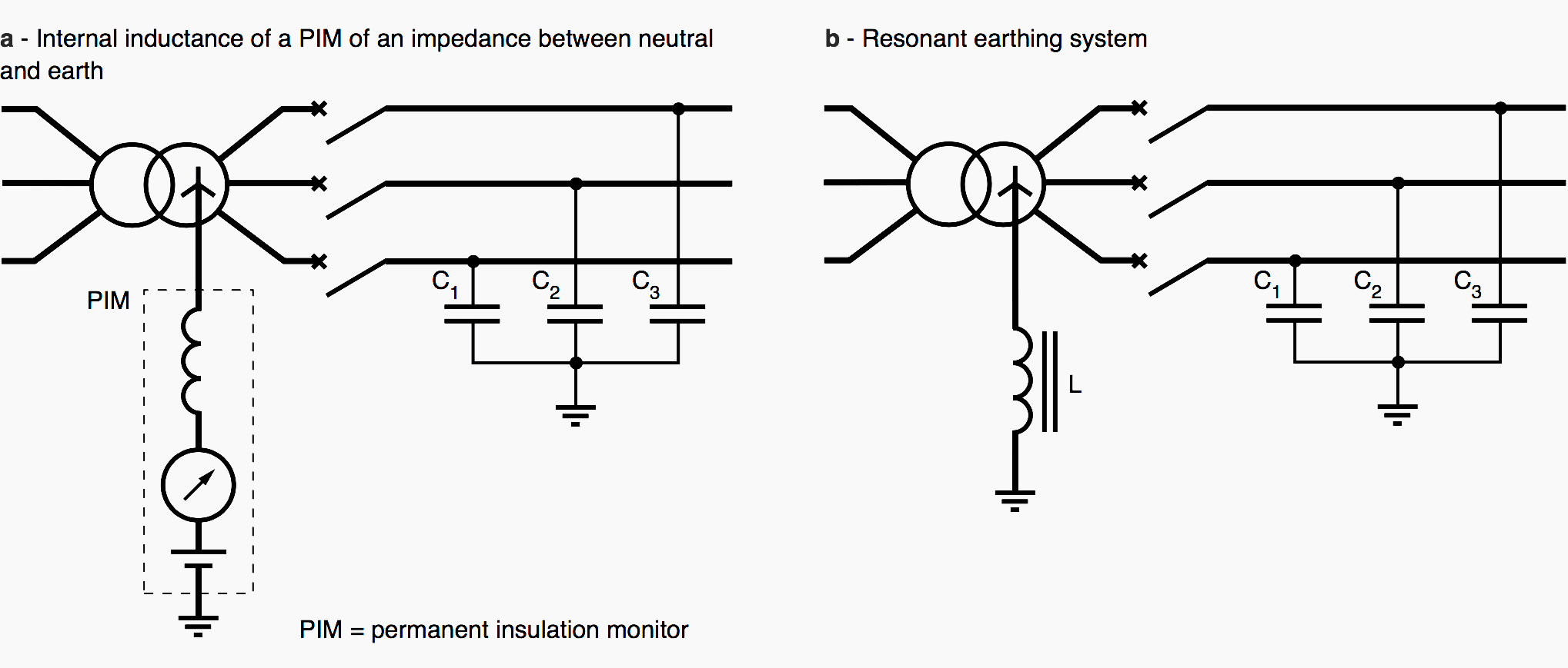
Overvoltages may cause sufficient potential rise of the neutral point to initiate ferroresonance between the inductance of the PIM and the capacitances to earth of the network
(see fig. 5a ).
Excitation and start of resonance of the circuit consisting of series connection of inductance L and capacitance 3×C0 may occur in the following cases:
- HV neutral of the HV/MV transformer earthed, and HV fault flowing through the earth conductor of the substation,
- Iron core saturation of the HV/MV transformer,
- Transformer design dissymmetry,
- Natural dissymmetry of the capacitances (C1, C2, C3 in figure 5b ) to earth.
This may result in saturation of the iron coil, thus initiating or sustaining ferroresonance.
6. Transformer supplied by a highly capacitive power system with low short-circuit power
Ferroresonance may occur when an unloaded power transformer is suddenly connected to a low short-circuit power source compared with transformer rated power through an underground cable or a long overhead line.
This is the case, for example, on return to service in an MV (underground cable) urban or industrial power networks, but also in very extended rural public MV power networks (see figure 6 ) or where underground cables are increasingly used (reliability and aesthetics).
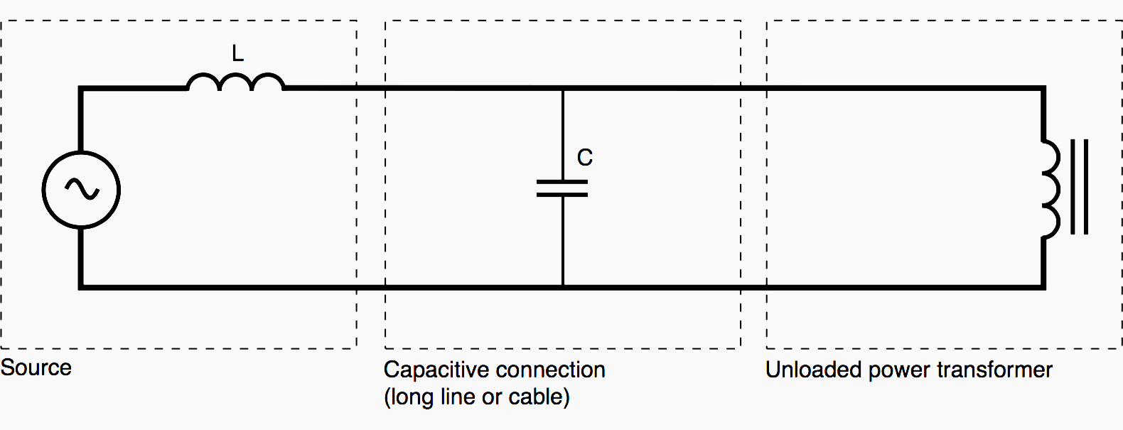
This parallel ferroresonance (capacitance parallel-connected on the transformer’s magnetizing inductance) is normally three- phase, of the fundamental or of the quasi- periodic type.
In short:
- Configurations under which ferroresonance can occur are endless.
- There are many different types of ferroresonance: single-phase, three-phase, common mode, differential mode.
- Experience, however, makes it possible to identify some configurations at risk which command some attention. These are:
- Voltage transformer connected between phase and earth on an isolated neutral system,
- Transformer fed through long and/or capacitive lines,
- Fuse protection, blowing of which results in non-multi pole breaking,
- Unloaded or lightly loaded power or voltage instrument transformer.
- The phenomena most likely to trigger ferroresonance are:
- Switching operation of capacitor banks and unloaded lines,
- Insulation faults,
- Lightning,
- Switching operation of unloaded transformers.
Preventing or damping ferroresonance
A number of practical measures can be taken to prevent ferroresonance, whose overvoltages, overcurrents and distortions wave forms result in thermal and dielectric stresses which may be dangerous for electrical equipment (failure, reduction in performance and lifetime of insulators…).
The various methods used are based on the following principles:
- Avoid, by proper design and/or switching operations, configurations susceptible to ferroresonance. This may involve prohibiting certain system configurations, and/or certain power system switching operations and/or certain switchgear.
- Ensure that system parameter values are not included (even temporarily) in an area at risk and if possible provide a safety margin with respect to danger areas.
- Ensure that the energy supplied by the source is not sufficient to sustain the phenomenon. This technique normally consists of introducing losses which damp out ferroresonance when it occurs.
Publication 71 of the IEC states that temporary ferroresonance (and resonance) overvoltages “shall be prevented or limited” (by one of the above means). “They shall not normally be considered as the basis for the surge arrester rated voltage, or for the insulation design unless these remedial measures are not sufficient”.
This means that the insulation co-ordination procedure does not normally take into account the overvoltage levels, and that, consequently, surge arresters (whose residual voltage is usually higher than the overvoltages due to ferroresonance) do not theoretically provide protection against it.
Reference // Ferroresonance by Ph. Ferracci; Schneider Electric
Related electrical guides & articles


Edvard Csanyi
Hi, I'm an electrical engineer, programmer and founder of EEP - Electrical Engineering Portal. I worked twelve years at Schneider Electric in the position of technical support for low- and medium-voltage projects and the design of busbar trunking systems.I'm highly specialized in the design of LV/MV switchgear and low-voltage, high-power busbar trunking (<6300A) in substations, commercial buildings and industry facilities. I'm also a professional in AutoCAD programming.
Profile: Edvard Csanyi

Please send me PDF file, thanks
Please send pdf Six network operating conditions under which ferroresonance can occur to me .
E-mail : [email protected]
Please i will need some pdf of your post.
Thank you
[email protected]