
Estimated Study Time: 13 minutes
Neutral conductor
The neutral conductor is a live conductor that is connected to the neutral point of the system and is able to contribute to the transmission of electric power. The neutral point is usually, but not necessarily connected to the star-point of the transformer or of the generator.
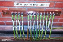
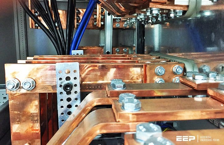 Essential considerations on the neutral and protective conductor in LV power system (photo credit: EEP)
In practice, in electrical installations, the neutral point of he system has zero potential. In fact, if the system is balanced, from the vector diagram f the phase-to-phase and of the star voltages, it results that the neutral point coincides with the centroid of the triangle.
Otherwise, if the connection is of delta type, the neutral point can be made accessible by deriving from the phases a set of three star-connected impedances of equivalent value.
The neutral conductor functions are:
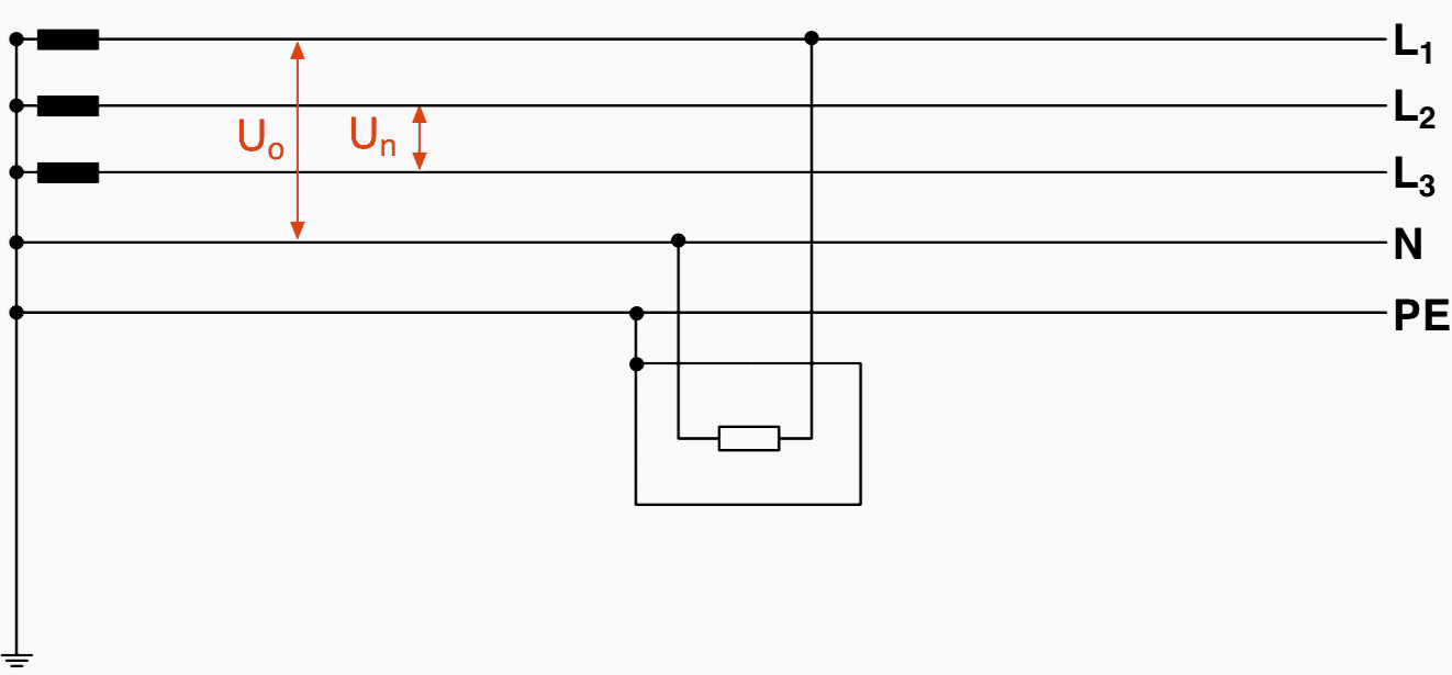
Function #1
Making available a voltage U0 that is different from the phase-to-phase voltage Un (see Figure 1).
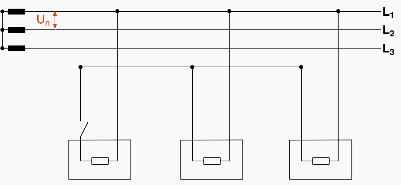
Function #2
Making the single phase loads functionally independent one from the other (Figure 2). With the neutral distributed the single-phase loads are always supplied by the voltage U0.

In absence of the neutral, the disconnection of a load could make the other loads operate at a voltage equal to Un/2.
Function #3
Without the neutral, the sum of the currents must be zero, which results in a strong dissymmetry of the phase voltages.

The presence of the neutral binds the real star point to the ideal one.

Function #4
Accomplishing also the function of protective conductor (PEN), under specific conditions (Figure 4). In TN-C system, the neutral conductor is also the protective conductor.

Protection and disconnection of the neutral conductor
Under abnormal conditions, the neutral conductor may have a voltage to earth which, for example, may be due to a disconnection caused by an accidental rupture or by the intervention of the single-pole devices (fuses or single-pole circuit-breakers).
Attention must be paid to the fact that these anomalies can have heavy consequences if the neutral conductor is used also as protective conductor like in TN-C systems.
As just seen, in a four-pole circuit, the disconnection of the neutral conductor only may alter the supply voltage of the single-phase apparatus which are supplied by a voltage different from the phase voltage.
Therefore, protection of the neutral conductor must not be provided by single-pole devices. Protection and disconnection of the neutral conductor are different according to the nature of the distribution systems: TT or TN systems and IT systems.
Tips for TT or TN systems
Tip #1 – Where the cross-sectional area of the neutral conductor is at least equal to or greater than that of the phase conductors, it is not necessary to provide overcurrent detection for the neutral conductor or a disconnecting device for that conductor (neutral not protected and not disconnected).
Tip #2 – Overcurrent detection does not need to be provided for the neutral conductor if the two following conditions are simultaneously fulfilled:
- The neutral conductor is protected against short-circuit by the protective device for the phase conductors of the circuit, and
- The maximum current likely to be carried by the neutral conductor is, in normal service, clearly lower than the value of the current-carrying capacity of that conductor;
Tip #3 – Where the cross-sectional area of the neutral conductor is less than that of the phase conductor, it is necessary to provide overcurrent detection for the neutral conductor, so that the disconnection of the phase conductors, but not necessarily of the neutral conductor, is caused (neutral protected but not disconnected).
In TN-C systems, the neutral conductor serves also as protective conductor and therefore it cannot be disconnected. Besides, in case of disconnection of the neutral conductor, during an earth fault the exposed-conductive-parts would take the rated voltage to earth of the system.
Tips for IT systems
Tip #1 – Where the neutral conductor is distributed, it is generally necessary to provide overcurrent detection for the neutral conductor of every circuit, which will cause the disconnection of all the live conductors of the corresponding circuit, including the neutral conductor.
Overload detection on the neutral conductor is not necessary if:
- The neutral conductor is effectively protected against the short-circuits by a protective device placed on the supply side (i.e. located at the origin of the installation).
- The circuit is protected by a residual current device with a rated residual current not exceeding 0.15 times the current-carrying capacity of the corresponding neutral conductor. This device shall disconnect all the live conductors, including the neutral.
Table 1 summarizes the items above (TT/TN-S, TN-C and IT systems):
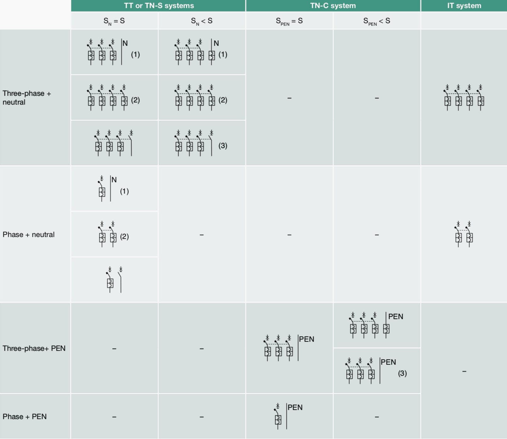
Where:
- Minimum requirement prescribed by the installation standards for TN-S systems only, whereas TT systems require the neutral conductor always disconnect
- Configuration suggested by ABB
- Feasible configuration if item b) is verified
Flowchart “protection of the neutral conductor”

Determination of the minimum cross-sectional area of the neutral conductor
The neutral conductor, if any, shall have the same cross-sectional area as the line conductor in the following two cases:
- In single or two-phase circuits, whatever the cross section of the line conductor is.
- In three-phase circuits, when the cross section of the line conductor is smaller than or equal to 16 mm2 in copper or 25 mm2 in aluminum.
The cross section of the neutral conductor can be smaller than the cross section of the phase conductor when the cross section of the phase conductor is greater than 16mm2 with copper cable or 25 mm2 with aluminum cable, if both the following conditions are met:
- The cross section of the neutral conductor is at least 16 mm2 for copper conductors and 25 mm2 for aluminum conductors.
- There is no high harmonic distortion of the load current. If there is high harmonic distortion, as for example in the case of discharge lamps, the cross section of the neutral cannot be smaller than the cross section of the phase conductors.
To summarize in Table 2:
| Phase cross section S [mm2] | Min. neutral cross-section SN [mm2] | |
| Single-phase/two-phase circuits Cu/Al | any | S* |
| Three-phase circuits Cu | S ≤ 16 | S* |
| S > 16 | 16 | |
| Three-phase circuits Al | S ≤ 25 | S* |
| S > 25 | 25 |
* In TN-C distribution systems, the Standards prescribe for the PEN conductors the minimum cross section of 10 mm2 if made by copper and 16 mm2 if by aluminum.
Protective conductor
Determination of the minimum cross sections
The minimum cross section of the protective conductor PE can be determined by using Table 3 below:
| Cross section of the phase conductor S [mm2] | Cross-sectional area of the protective conductor SPE [mm2] |
| S ≤ 16 | S |
| 16 < S ≤ 25 | 16 |
| S > 25 | S / 2 |
For a more accurate calculation and assuming that the protective conductor is subjected to adiabatic heating from an initial known temperature to a final specified temperature (therefore applicable for fault extinction times no longer than 5s), the minimum cross-section of the protective conductor SPE can be obtained by using the following formula:
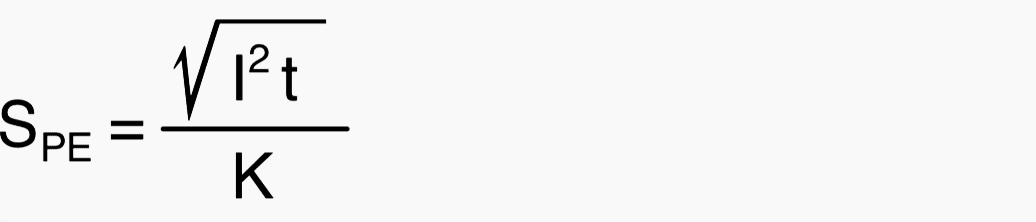
where:
- SPE is the cross section of the protective conductor in [mm2]
- I is the r.m.s. current owing through the protective conductor in the event of a fault with low impedance in [A]
- K is a constant which depends on the material of the protective conductor, on the type of insulation and on the initial and final temperature.
Constant K can be taken from the tables of the Standards or calculated with the following formula:

where:
- Qc is the thermal capacity per unit of volume of the conductor material in [J/°C×mm3]
- B is the inverse of the temperature coefficient of the resistivity at 0° C for the conductor
- ρ20 is the resistivity of the conductor material at 20°C in [Ω×mm]
- θi is the initial temperature of the conductor in [°C]
- θf is the nal temperature of the conductor in [°C]
θi and θf depend both on the insulating material as well as on the type of cable used. For further details refer to the Standard.
Table 4 shows the most common values of the above mentioned parameters:
| Material | B [°C] | Qc [J/°C∙mm3] | ρ20 [Ω∙mm] | 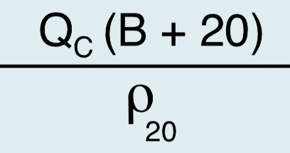 |
| Copper | 234.5 | 3.45×10⁻³ | 17.241×10⁻⁶ | 226 |
| Aluminium | 228 | 2.5×10⁻³ | 28.264×10⁻⁶ | 148 |
| Lead | 230 | 1.45×10⁻³ | 214×10-6 | 42 |
| Steel | 202 | 3.8×10⁻³ | 138×10-6 | 78 |
If the table of the Standards or the formula do not provide a standardized cross section, it is necessary to choose a protective conductor with the immediately larger standardized cross-section.
Regardless of whether the table or the formula is used, the cross section of the protective conductor, which is not a part of the supply cable, shall be at least:
- 2.5 mm2 if a mechanical protection is provided
- 4 mm2 if no mechanical protection is provided
Reference // Distribution systems & protection against indirect contact and earth fault by ABB
Related electrical guides & articles


Edvard Csanyi
Hi, I'm an electrical engineer, programmer and founder of EEP - Electrical Engineering Portal. I worked twelve years at Schneider Electric in the position of technical support for low- and medium-voltage projects and the design of busbar trunking systems.I'm highly specialized in the design of LV/MV switchgear and low-voltage, high-power busbar trunking (<6300A) in substations, commercial buildings and industry facilities. I'm also a professional in AutoCAD programming.
Profile: Edvard Csanyi

Need your help, as i am researching on best and safest grounding methods for pmt as to prevent human loss would you pls suggest me what to use on LV side of pmt in between neutral and ground to prevent return current to choose wrong path and not to travel from human body
So helpful
As Kiow & Tiwari point out, in fig.2b, none of the appliances will work at all ! In fig. 2a, it’s not important that all appliances are shown connected to L1, but I don’t think that’s what the author intended. In fig.3a, the appliances don’t work at all, and in fig.3b, if the labels IL1 IL2 & iL3 make sense only if all three lines are connected.
The table for protective conductor cross-sections should say that these figures apply to a *separate* protective conductor. Many cables in common use don’t conform to the tabulated figures. For instance for the standard oval-shaped pvc insulated / pvc-sheathed cables often used in domestic & light commercial environments, the 4 sq.mm cable has a protective-conductor cross-section of 1.5 sq.mm, and the 6 sq.mm size has a protective conductor of 2.5 sq.mm.
(Maybe they should conform; it would make it much easier to achieve the required earth-loop impedances, but that’s another matter !)
I agree to your comment. The author’s statement will hold only if the loads are connected to separate phases instead of a single phase in figures 2a, 3a and 3b.
This is a wonderful space for our community. I have more than 20 years of experience working with electrical system in the design and construction fields and I feel that I can learn every day with those articles.
Thank you Mr. Edvard for your help.
There are some errors in some of the drawings. The loads should have been connected to the 3-phases and not to 1-phase.
In Function 2 and 3 explanations,In diagram all the loads are connected to LINE 1.
Looks like printing mistake.pls confirm.
Apologies for earlier confusing message, thanks to ‘predictive text’. Thank you for writing such an informative articel. I must, though, take issue with you on your terminology.
What I was trying to say is that, while widely- (but incorrectly-) used in the field, the expression, ‘phase-to-phase’ voltage is actually incorrect and meaningless, and only confuses students who are learning about three-phase a.c. systems. The correct term is ‘line-to-line’ voltage.
The reason I say that ‘phase-to-phase’ voltage is meaningess is because the conductors that interconnect the supply and load are correctly termed ‘lines’, NOT ‘phases’, so the voltages between them are correctly termed ‘line voltages’ or ‘line-to-line voltages’. It’s only possible to have voltages ACROSS individual phases; there cannot be voltages FROM one phase TO another (phase-to-phase); it simply makes to sense.
It’seems ‘line to line’ voltage NOT ‘phase to phase’ voltage. Your use of ‘phase to phase’ confuses students.