
Estimated Study Time: 28 minutes
Introduction to numerical relays
The distinction between digital and numerical relays is particular to Protection. Numerical relays are natural developments of digital relays due to advances in technology. They use one or more digital signal processors (DSP) optimised for real time signal processing, running the mathematical algorithms for the protection functions.
 The Essentials Of Numerical Relays, Their Features And Important Considerations
The continuing reduction in the cost and size of microprocessors, memory and I/O circuitry leads to a single item of hardware for a range of functions. For faster real time processing and more detailed analysis of waveforms, several DSPs can be run in parallel.
Many functions previously implemented in separate items of hardware can then be included in a single item.
Ok, let’s start with introduction to numerical relays, then explaining their additional features and at the end to discuss important considerations regarding software, data management, etc..
- Introduction to numerical relays
- Additional Features Of Numerical Relays
- Numerical Relay Considerations
Table 1 provides a list of typical functions available, while Table 2 summarises the advantages of a modern numerical relay over static relay equivalents.
TABLE 1 – Numerical distance relay features
| Distance Protection – several schemes including user definable | Overcurrent Protection (directional/non-directional) |
| Several Setting Groups for protection values | Switch-on-to-Fault Protection |
| Power Swing Blocking | Voltage Transformer Supervision |
| Negative Sequence Current Protection | Undervoltage Protection |
| Overvoltage Protection | CB Fail Protection |
| Fault Location | CT/VT Supervision |
| Autoreclose | Check Synchronisation |
| CB State Monitoring | CB Condition Monitoring |
| Broken Conductor Detection | User-Definable Logic |
| Fault/Event/Disturbance recorder | Measurement of Power System Quantities (Current, Voltage, etc.) |
TABLE 2 – Advantages of numerical relays over static relays
| Several setting groups | Wider range of parameter adjustment |
| Communications built in (serial, Ethernet, teleprotection, etc.) | Internal Fault diagnosis |
| Power system measurements available | Distance to fault locator |
| Disturbance recorder | Auxiliary protection functions (broken conductor, negative sequence, etc.) |
| CB monitoring (state, condition) | User-definable logic |
| Backup protection functions in-built | Consistency of operation times – reduced grading margin |
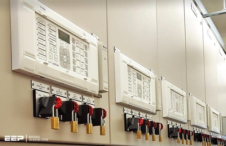
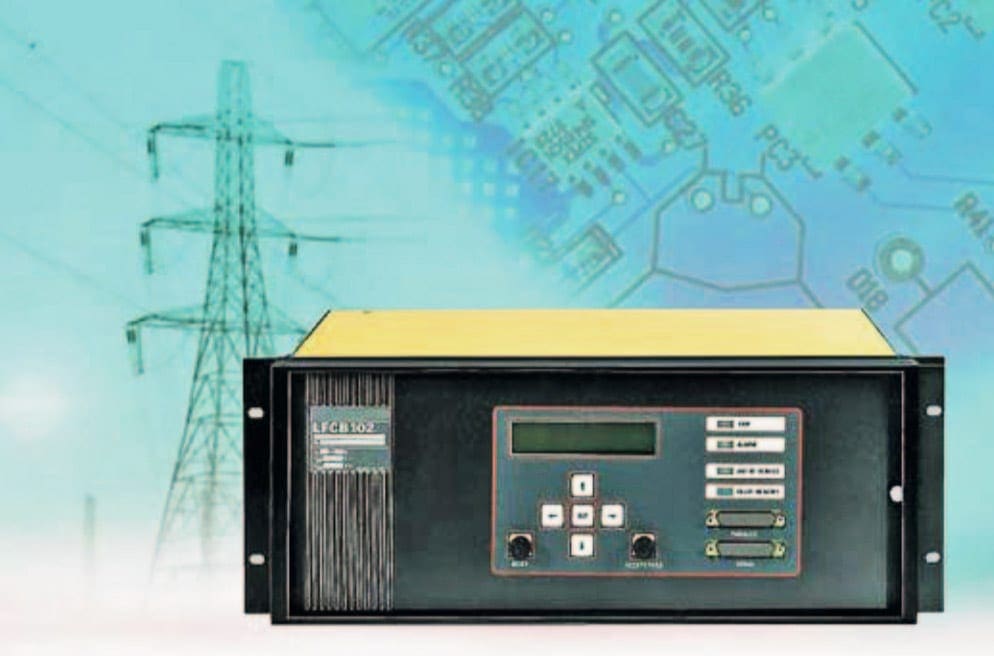
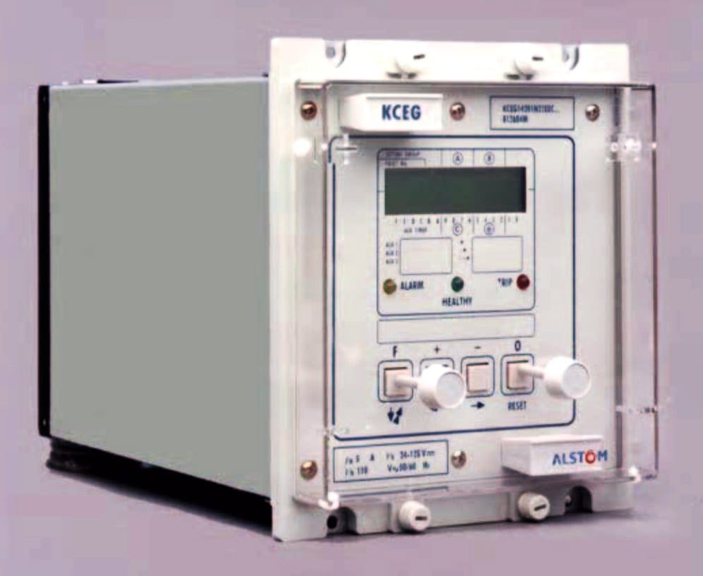
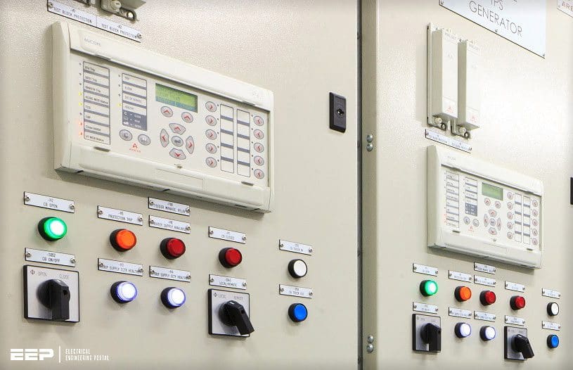
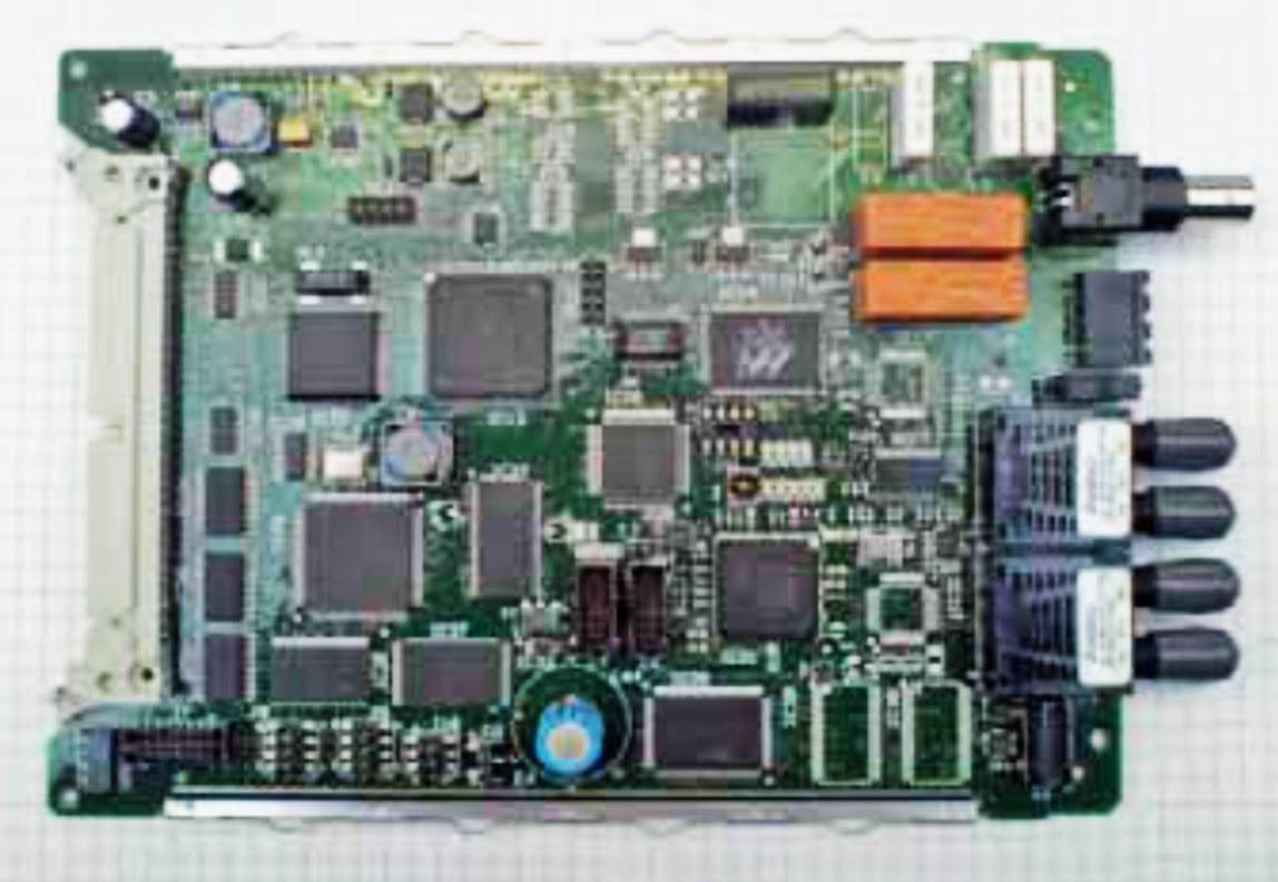
Figure 1, Figure 2 and Figure 3 show typical numerical relays, while Figure 4 and Figure 5 show typical numerical relay boards.
A numerical relay has the functionality that previously required several discrete relays, therefore the relay functions such as overcurrent or earth fault are referred to as ‘relay elements’.
Each relay element is in software so with modular hardware the main signal processor can run a vast variety of relay elements.

The argument against putting many features into one piece of hardware centres on the issues of reliability and availability. A failure of a numerical relay may cause many more functions to be lost, compared to applications where different functions are implemented by separate hardware items.
Comparison of reliability and availability between the two methods is complex as inter-dependency of elements of an application provided by separate relay elements needs to be taken into account.
Practical experience indicates that numerical relays are as reliable as relays of earlier technologies. Modern numerical relays will have comprehensive self monitoring to alert the user to any problems.
1. Hardware Architecture
The typical architecture of a numerical relay is shown in Figure 6. It consists of one or more digital signal processors, some memory, digital and analogue input/output (I/O), and a power supply.
Where multiple processors are used, one of them is a general controller of the I/O, Human Machine Interface (HMI) and any associated logic while the others are dedicated to the protection relay algorithms.
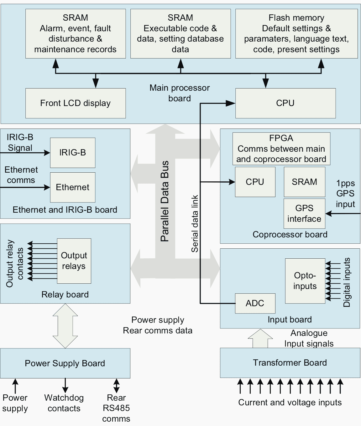
By organising the I/O on a set of plug-in printed circuit boards (PCBs), additional I/O up to the limits of the hardware / software can be easily added. The internal communications bus links the hardware and therefore is a critical component in the design.
It must work at high speed, use low voltages, yet be immune to conducted and radiated interference from the electrically noisy substation environment.
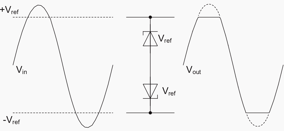
Additionally, the input signals must be amplitude limited to avoid them exceeding the measurement range, otherwise the waveform is clipped, introducing harmonics.
See Figure 7.
Analogue signals are converted to digital form using an A/D converter. The cheapest method is to use a single A/D converter, preceded by a multiplexer to connect each of the input signals in turn to the converter. The signals may be initially input to several simultaneous sample-and–hold circuits before multiplexing, or the time relationship between successive samples must be known if the phase relationship between signals is important.
The alternative is to provide each input with a dedicated A/D converter and logic to ensure that all converters perform the measurement simultaneously.
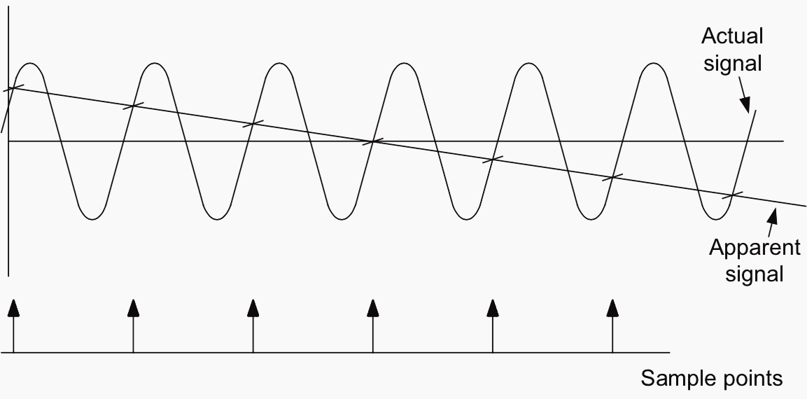
The frequency of sampling must be carefully considered, as the Nyquist criterion applies:
fs ≥ 2 × fh
where:
- fs = sampling rate
- fh = highest frequency of interest
If the sampling frequency is too low, aliasing of the input signal can occur (see Figure 8) so that high frequencies can appear as part of the signal in the frequency range of interest. Incorrect results are then obtained.
Digital sine and cosine filters (Figure 7) extract the real and imaginary components of the signal.
2. Relay Operating System Software
The software provided is commonly organised into a series of tasks operating in real time. An essential component is the Real Time Operating System (RTOS) which ensures that the other tasks are executed when required, in the correct priority.
Other software depends on the function of the relay, but can be generalized as follows:
- System services software – This is comparable with the BIOS of an ordinary PC and controls the low-level I/O for the relay such as drivers for the relay hardware and boot-up sequence.
- HMI interface software – This is the high level software for communicating with a user on the front panel controls or through a data link to another computer to store data such as settings or event records.
- Application software – This is the software that defines the protection function of the relay
- Auxiliary functions – Software to implement other features in the relay, often structured as a series of modules to reflect the options offered by the manufacturer.
3. Relay Application Software
The relevant software algorithm is then applied. Firstly the quantities of interest are determined from the information in the data samples. This is often done using a Discrete Fourier Transform (DFT) and the result is magnitude and phase information for the selected quantity. This calculation is repeated for all of the quantities of interest.
The quantities can then be compared with the relay characteristic, and a decision made in terms of the following:
- Value above setting – start timers, etc.
- Timer expired – action alarm/trip
- Value returned below setting – reset timers, etc.
- Value below setting – do nothing
- Value still above setting – increment timer, etc.
Since the overall cycle time for the software is known, timers are generally implemented as counters.
Additional Features Of Numerical Relays
The digital signal processor (DSP) in a numerical relay normally can handle both the relay protection function calculations and general management of the relay such as HMI and I/O. However, if the DSP is overloaded it cannot complete the protection algorithm calculations in the required time and the protection function is slowed.
Function parameters are usually displayed on the front panel of the relay and through an external communications port.
- Measured Values Display
- VT/CT Supervision
- CB Control/State Indication / Condition Monitoring
- Disturbance Recorder (Oscillograph)
- Time Synchronization
- Programmable Logic
- Provision of Setting Groups
- Conclusions
1. Measured Values Display
This is perhaps the most obvious and simple function to implement, as it involves the least additional processor time. The values that the relay must measure to perform its protection function have already been acquired and processed.
Several extra quantities may be derived from the measured quantities, depending on the input signals available. These might include:
- Sequence quantities (positive, negative, zero)
- Power, reactive power and power factor
- Energy (kWh, kVArh)
- Max. demand in a period ( kW, kVAr; average and peak values)
- Harmonic quantities
- Frequency
- Temperatures/RTD status
- Motor start information (start time, total no. of starts/reaccelerations, total running time
- Distance to fault
The accuracy of the measured values can only be as good as the accuracy of the transducers used such as VTs CTs, and the A/D converter. As CTs and VTs for protection functions may have a different accuracy specification to those for metering functions, such data may not be sufficiently accurate for tariff purposes.
However, it is sufficiently accurate for an operator to assess system conditions and make appropriate decisions.
2. VT/CT Supervision
If suitable VTs are used, supervision of the VT/CT supplies can be made available. VT supervision is made more complicated by the different conditions under which there may be no VT signal, some of which indicate VT failure and some occur because a power system fault has occurred.
However, this technique fails when closing onto a dead but healthy line, so a level detector is also required to distinguish between current inrush due to line charging and that due to a fault.
CT supervision is carried out more easily. The general principle is the calculation of a level of negative sequence current that is inconsistent with the calculated value of negative sequence voltage.
3. CB Control and State Indication / Condition Monitoring
System operators normally require knowledge of the state of all circuit breakers under their control. The CB position-switch outputs can be connected to the relay digital inputs and therefore provide the indication of state through the communications bus to a remote control centre.
A numerical relay can record all of these parameters and hence be configured to send an alarm when maintenance is due.
If maintenance is not carried out within a predefined time or number of trips after maintenance is required, the CB can be arranged to trip and lockout or inhibit certain functions such as auto-reclose.
Finally, as well as tripping the CB as required under fault conditions, it can also be arranged for a digital output to be used for CB closure, so that separate CB close control circuits can be eliminated.
4. Disturbance Recorder (Oscillograph)
The relay memory requires a certain minimum number of cycles of measured data to be stored for correct signal processing and detection of events. The memory can easily be expanded to allow storage of a greater time period of input data, both analogue and digital, plus the state of the relay outputs.
It may be inconvenient to download the record immediately, so facilities may be provided to capture and store a number of disturbances.
In industrial and small distribution networks, this may be all that is required. In transmission networks, it may be necessary to provide a single recorder to monitor several circuits simultaneously, and in this case, a separate disturbance recorder is still required.
For more information on the different types of disturbance recording, read this technical article.
5. Time Synchronization
Disturbance records and data relating to energy consumption requires time tagging to serve any useful purpose. Although there is an internal clock, this is of limited accuracy and use of this clock to provide time information may cause problems if the disturbance record has to be correlated with similar records from other sources to obtain a complete picture of an event.
Many numerical relays have the facility for time synchronisation from an external clock. The standard normally used is an IRIG-B or IEEE 1588 signal, which may be derived from several sources including a GPS satellite receiver.
6. Programmable Logic
Logic functions are well suited to implementation using microprocessors. The implementation of logic in a relay is not new, as functions such as intertripping and auto-reclose require a certain amount of logic.
For instance, an overcurrent relay at the receiving end of a transformer feeder could use the temperature inputs provided to monitor transformer winding temperature and provide alarm or trip facilities to the operator or upstream relay, eliminating the need for a separate winding temperature relay.
There may be other advantages such as different logic schemes required by different utilities that no longer need separate relay versions, or some hard-wired logic to implement, and all of these reduce the cost of manufacture.
It is also easier to customize a relay for a specific application, and eliminate other devices that would otherwise be required.
7. Provision of Setting Groups
Historically, electromechanical and static relays have been provided with fixed plug settings applied to the relay. Unfortunately, power systems change their topology due to operational reasons on a regular basis, such as supply from normal or emergency generation. Different configurations may require different relay settings to maintain the desired level of network protection.
Fault levels are significantly different on parts of the network that are energized under normal and emergency generation.
This may obviate the need for duplicate relays to be fitted with some form of switching arrangement of the inputs and outputs depending on network configuration. Also the operator can program the relay remotely with a group of settings if required.
Conclusions
The extra facilities in numerical relays may avoid the need for other measurement and control devices to be fitted in a substation. Also numerical relays have functionality that previously required separate equipment. The protection relay no longer performs a basic protection function but is an integral and major part of a substation automation scheme.
The choice of a protection relay rather than some other device is logical as the protection relay is probably the only device that is virtually mandatory on circuits of any significant rating.
Therefore the functions previously carried out by separate devices such as bay controllers, discrete metering transducers and similar devices are now found in a protection relay. It is now possible to implement a substation automation scheme using numerical relays as the main hardware provided at bay level.
As the power of microprocessors continues to grow and pressure on operators to reduce costs continues, this trend will continue. One obvious development is the provision of RTU facilities in designated relays that act as local concentrators of information within the overall network automation scheme.
Numerical Relay Considerations
The introduction of numerical relays replaces some of the issues of previous generations of relays with new ones. Some of the new issues that must be addressed are as follows:
1. Software Version Control
Numerical relays perform their functions in software. The process used for software generation is no different in principle to that for any other device using real-time software, and includes the difficulties of developing code that is error-free.
This process then requires a rigorous system of software version control to keep track of:
- The different software versions in existence x the differences between each version
- The reasons for the change
- Relays fitted with each of the versions
With an effective version control system, manufacturers are able to advise users in the event of reported problems if the problem is a known software related problem and what remedial action is required. With the aid of suitable software held by a user, it may be possible to download the new software version instead of requiring a visit from a service engineer.
2. Relay Data Management
A numerical relay usually provides many more features than a relay using static or electromechanical technology. To use these features, the appropriate data must be entered into the relay’s memory and it is good practice to keep a backup copy.
The amount of data per numerical relay may be 10-100 times that of an equivalent electromechanical relay, to which must be added the possibility of user-defined logic functions.
The task of entering the data correctly into a numerical relay becomes a much more complex task than previously, which adds to the possibility of a mistake being made. Similarly, the amount of data that must be recorded is much larger, requiring larger storage.
A copy of the setting data (including user-defined logic schemes where used) can also be stored on the computer. These can then be printed or uploaded to the user’s database facilities.
3. Relay Testing and Commissioning
Numerical relays perform many more functions than earlier generations of relays so testing them is more complex. Site commissioning is usually restricted to running the in-built software self-check, verifying that currents and voltages measured by the relay are correct, and exercising a subset of the protection functions.
Any problems revealed by such tests require specialist equipment to resolve so it is simpler to replace a faulty relay and send it for repair.

Reference // Network Protection & Automation Guide by Alstom Grid
Related electrical guides & articles


Edvard Csanyi
Hi, I'm an electrical engineer, programmer and founder of EEP - Electrical Engineering Portal. I worked twelve years at Schneider Electric in the position of technical support for low- and medium-voltage projects and the design of busbar trunking systems.I'm highly specialized in the design of LV/MV switchgear and low-voltage, high-power busbar trunking (<6300A) in substations, commercial buildings and industry facilities. I'm also a professional in AutoCAD programming.
Profile: Edvard Csanyi

I need electrical wiring