
Estimated Study Time: 25 minutes
The History of Numerical Relays
The first protection devices based on microprocessors were employed in 1985. The widespread acceptance of numerical technology by the customer and the experiences of the user helped in developing the second generation numerical relays in 1990. Modem power system protection devices are built with integrated functions. Multi-functions like protection, control, monitoring and measuring are available today in numeric power system protection devices.
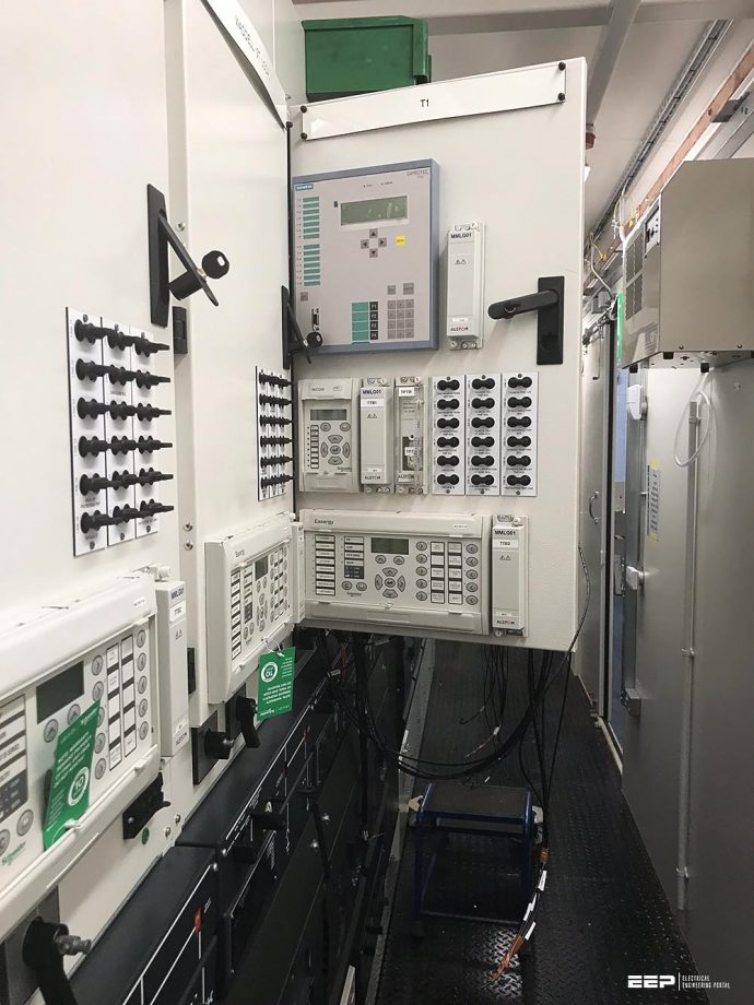 The facts about numerical relays that every electrical engineer should know (photo credit: NSS Ltd.)
Also, the communication capability of these devices facilitates remote control, monitoring and data transfer. Traditionally, electromechanical and static protection relays offered single-function, single characteristics, whereas modern numeric protection offers multi-function and multiple characteristics. Some protections also offer adaptable characteristics, which dynamically change the protection characteristic under different system conditions by monitoring the input parameters.
The measuring principles and techniques of conventional relays (electromechanical and static) are fewer than those of the numerical technique, which can differ in many aspects like the type of protection algorithm used, sampling, signal processing, hardware selection, software discipline, etc.
The following sections cover relay hardware, relay software, multiple protection characteristics, adaptive protection characteristics, data storage, instrumentation feature, self-check feature, communication capability, additional functions, size and cost-effectiveness.
- Relay Hardware
- Relay Software
- Multiple Protection Characteristics
- Adaptive Protection Characteristics
- Data Storage
- Instrumentation
- Self-check Relay Feature
- Relay Communication
- Additional Functionality of Numerical Relays
- Size of Numerical Relays
- Cost of Numerical Relays
- HV and Environment Testing
- Let’s Make the Conclusion
1. Relay Hardware
Numerical relays use a specialised digital signal processor (DSP) as the computational hardware, along with associated software tools. The relaying voltage and currents are passed through an isolation transformer. The voltage inputs of the relay are scaled down from the nominal voltage to a low level determined by the ADC (analogue-to-digital converter) input range.
The current inputs to the relay are scaled down from nominal 5/1 A and are converted into equivalent voltages. These scaled signals are filtered by using a low-pass filter to prevent a liasing of the high-frequency components into the fundamental frequency component. The filtered signals are multiplexed using an analogue multiplexer and amplified, if needed, by using a programmable gain amplifier. The multiplexed analogue signal is sampled and converted into digital data using the ADC.
The more complex relay uses multi-processor architecture wherein the digital signal processor executes complex algorithm calculations and the host processor performs all the other tasks.
Communication between the processors is provided by the dual-ported memory. Flash memory is used for storing the programme and RAM (random access memory) is used for temporary storage of variables, target information and oscillography. Contact inputs and outputs, user inter-face (keyboard and liquid crystal display) and the serial communication ports (RS-232 and RS-485) are interfaced to the host processor.
The digital signal processor executes a variety of signal processing algorithms to estimate several parameters of the digitized voltage and current signals, and transfers them to dual-ported memory. The host processor receives these parameters from the dual-ported memory and per-forms relay logic and other timing functions to generate appropriate trip or alarm output signals.
The host processor, running under a multi-tasking operating system, also performs several other tasks including communications, set-point updates, target updates and user interface.
The analogue signal inputs (voltage and current), contact status inputs and communication circuits are conditioned and protected to withstand the harsh electrical and environmental conditions of the sub-station and power plant. The design of the relay input, output and power supply circuits must incorporate filtering to reduce EMI (electromagnetic interference).
The primary method of reducing unwanted induced AC voltage is to bypass these voltages to ground with capacitors. Other components such as varistors, chokes and ferrite beads, are also applied to suppress surge voltages and EMI.
2. Relay Software
The software provided in a numerical relay is commonly organized in a series of tasks operating in real time. The main component is the real time operating system (RTOS) whose function is to ensure that other tasks are executed as and when required on a priority basis. The software provided will vary on the basis of the following relay-specific functions.
- System services software – This controls the low level I0 for the relay (i.e. drivers for the relay hardware, boot-up sequence, etc.).
- HMI interface software – This is a high level software for communication with the user via front panel controls that are connected through a data link to another computer running suitable software, storage and setting data.
- Application software – This is a software that defines the protection function of the relay.
- Auxiliary function – This software implements other features offered in the relay. The reliability of software in the digital relay is critical to the overall reliability of the product. The majority of software problems in digital relays can be attributed to design and implementation errors.
Following are some of the key tests to be conducted at various design phases of digital multi-function relays:
- Relay algorithm simulation testing
- Static functional testing
- Dynamic functional testing
- Environmental and hardware-related tests
- Site installation and testing
Recommended reading: Commissioning of protection relays using test equipment and software
Commissioning of protection relays using test equipment and software
3. Multiple Protection Characteristics
In simple Inverse definite minimum time lag (IDMTL) overcurrent and earth fault relays, multiple characteristics like NI, VI, El, LTI and DTL characteristics are available in relay and the required characteristics can be selected at site.
4. Adaptive Protection Characteristics
Numerical relays can adapt themselves to different system conditions by monitoring the operat-ing quantities from the digital inputs of the relay. Some examples of these adaptions are:
Adaption #1 – In motor protection relay, different settings can be adapted for the starting condition and running condition. Overcurrent protection, earth fault protection, unbalance protection and stall protection cannot be set at a very sensitive level during start-up because the starting current will influence these settings.
Adaption #2 – In transformer protection relay, the third slope is called the bias slope limit, which is used to afford greater stability and this can be achieved by monitoring the through fault current. Once the through fault current is above the set value, the relay bias automatically increases to facilitate greater stability for through fault condition.
Adaption #3 – In distance relays, for different system configurations like parallel feeder in, and parallel out and grounded, different settings can be adapted for this condition.
Adaption #4 – In IDMTL relays, depending upon the system condition like the number of incomers and outgoing feeders, different settings can be selected and better protection can be achieved.
5. Data Storage
In numerical relay data storage is done in three formats, i.e. fault record, event record and waveform record. Fault record gives the complete information about the fault, i.e. fault current magnitude, type of fault, fault phase details, etc. with time stamping. Also in motor protection relays, additional information pertaining to positive sequence, negative sequence, equivalent current and difference current (between phases) is available.
Similarly in distance relays fault location is also possible. The fault record gives all information about the fault to the operating personnel. Event record stores inside the relay all the changes taking place in the system like protection element, pick-up, and drop-off operation, output and input energization and setting change, etc.
All the events are time-stamped. Waveform record stores the analogue and digital channel values during the relay operation or on demand. This record gives the nature of fault waveforms (transient) and instantaneous values, etc.
It is also possible to calculate the relay operating time and breaker operating time.
These records can also be converted into the ‘comtrade’ format, with which data can be played back into the relay using the digital test system. The records can also be manually triggered and viewed to verify the phase relationship during commissioning. These records can also be fed to the harmonic analyzer software to find out the harmonic content in the fault quantities.
6. Instrumentation
Numerical relays are provided with a metering function and separate panel mounted meters can be eliminated. Some relays can also give the energy meter function.
The relay provides metering facility, where the operating personnel can view online different parameters and these metering features can be used as a valuable tool during the commissioning period when primary injection is carried out. This is perhaps the most obvious and simplest function to implement, as it involves the least additional processor time.
A number of extra quantities can be derived from the measured quantities, depending upon the input signals available. These may include:
- Sequence quantities (positive, negative, zero)
- Power, reactive power and power factor
- Energy (kWh, kvarh)
- Maximum demand in a period (kW, kvar; average and peak values)
- Harmonic quantities
- Frequency
- Temperatures /RTD status
- Motor start information (start time, total number of starts/re-accelerations, total running time)
- Distance to fault
The accuracy of the measured values can only be as good as the accuracy of the transducers used (VTs, CTs, A/D converter, etc.). As CTs and VTs used for protection functions may have a different accuracy specification than those used for metering functions, such data cannot be sufficiently accurate for tariff purposes.
However, it is sufficiently accurate for an operator to assess the system conditions and take appropriate decisions.
In motor protection relay, the instrumentation mode can also display motor status, time to trip (during abnormal condition), time to start (if the protection is locked out), the last starting time, last starting current, positive, negative, difference current values, etc.
7. Self-check Feature
Self-diagnostics is one of the most important features of numerical relays; it was not available in either electromechanical or static relay design. The ability to detect and correct a failure before the protection system has to operate is in contrast to the traditional protection system wherein a relay failure remains undetected until it fails to operate correctly during an event or until the next maintenance test
The most important self-diagnostic functions implemented in digital multi-function relays are detailed below.
7.1 Data Acquisition System Testing
Power supply voltages and ground are connected to the analogue input channels of the multiplexer and checked against warning and failure thresholds. This also verifies the analogue data acquisition system including multiplexer, programmable gain amplifier and ADC. The ADC’s conversion time is also checked to see if it is within the specification.
7.2 Memory Testing
The flash ROM contents are checked by calculating the check-sum and comparing it with the pre-computed and stored check-sum. The check-sum is calculated as the modul-256 sum of all the bytes. The RAM is tested by writing and reading a test pattern.
7.3 Set-point Testing
Set-points are stored in the serial EEPROM and a copy of these set-points is also stored in the RAM for executing relay logic. Whenever any set-point is changed, the check-sum of the set-points is calculated from the contents of the EEPROM. This check-sum is then compared with the calculated check-sum of the set-points stored in the RAM every time a set-point task is executed.
7.4 Watchdog Timer
The relay hardware design includes a watchdog timer re-set circuit to take the processor through an orderly re-set should the programme get lost due to hardware/software glitches.
Interesting reading: Fault event reconstruction using data pulled from intelligent electronic devices (IEDs)
Fault event reconstruction using data pulled from intelligent electronic devices (IEDs)
8. Communication
Communication makes the relay more intelligent and the operating personnel can set the relay and also download the fault information. It is also possible to upload the revised software to the relay at site without sending the relay back to the manufacturer.
Thus improvements in numerical relays can be upgraded at site without despatching the relay to the manufacturer which reduces the relay downtime.
Numerical relays carry out the processing of input quantities using a digital technique. The processed data can be accessed through the relay communication port. Although a separate high-end communication system is available today for numerical relay data communication and control, a simple communication system is also possible for remote control and monitoring using telephone line as a communication medium.
IEC 61850
In a nutshell, in the conventional protection schemes, all primary equipment such as circuit breakers, CT/VTs and power transformers are connected to the secondary system using the hardwires. There is normally a single function in the old relays so that lots of equipment are used to protect, control and monitor a substation bay.
On the other hand, in the modern protection schemes, smart protection relays support more functions in one piece of device. This is the result of the huge development of computer technologies that are used in power system protection. So a single intelligent device can support different functions such as protection, control, metering and fault recording.
IEC 61850 based solutions are now supporting a full interoperability between intelligent electronic devices (IED) from different manufactures. Utilities are now demanding IEC 61850 capabilities available in any substation related hardware or software.
Recommended reading: IEC 61850 for digital substation automation systems
9. Additional Functionality
Modern numerical relays have other additional functions like:
- Circuit breaker fail
- Loss of load, conductor broken
- Trip circuit supervision
- Circuit breaker conditions monitoring including programmable digital output and inputs for various logic build generally for blocking
- Auxiliary relays like Buchholz relay alarm/trip, and winding temperature alarm/trip contacts, which can be connected to relay as logic input and details of relay operation can be seen in the event log sheet.
- The relay user can also make custom built logic by using internal elements and inputs, i.e. VT/CT supervision.
Recommended reading: Mastering switchgear control circuits – AC/DC circuits and circuit breaker closing circuit
Mastering switchgear control circuits – AC/DC circuits and circuit breaker closing circuit
10. Size of Numerical Relays
The size of the numerical relays is much less as compared to that of electromechanical and static relays due to the multi-functionality approach of the former. For example, we have the following protections in numerical relays in-built into one relay.
Motor Protection Features Available:
- Thermal protection
- Unbalance protection
- Undercurrent protection
- Overcurrent and earth fault protection, and temperature protection
- Number of starts
- Hour run meter
- Ammeter
All these functions can be built into one relay, which will be very compact in size and also reduced weight.
11. Cost of Numerical Relays
Modern numerical protection devices have multiple protection elements and this technique makes the cost of the relay comparable with that of electromechanical and static relays (discrete). The cost of the microprocessor and digital hardware is falling day by day and the end-user can get a cost benefit in numerical relays in terms of greater functionality at a reduced price.
The following cost reduction benefit the consumer:
- The number of protective relays and auxiliary relays are reduced.
- CT and PT of lower VA burden are sufficient. Thus the cost of CT and PT is reduced.
- The panel space required is very less. Thus the size of instrument panels is reduced, thereby resulting in further cost reduction.
- The wiring of relay is much less as compared to electromechanical relays/static relays. This adds to savings in wiring material and labour.
12. HV and Environment Testing
Numerical relays are tested as per IEC 255-5 for dielectric, impulse voltage and insulation resistance. It should be suitable for 2 kV dielectric voltage, 5 kV impulse voltage and insulation resistance > than 1000 M-ohms.
12.1 Electrical Environment
Relay is tested for high frequency disturbance, fast transient, electrostatic discharge, radio frequency and impulse as per IEC 1000-4 and ANSI 37.90.
12.2 Atmospheric Environment
A relay is generally suitable for temperature as per IEC 255-6 for storage at -25°C to +70°C, and for operation at -25°C to +55°C. A relay is generally suitable for humidity as per IEC 68-2-3, for enclosure protection IP 52 as per IEC 529, for siesmic, shocks and bumps as per IEC 255-21 for Class 1 and for Class for vibration test as per IEC 255-21.
Recommended reading: Testing protection IEDs in IEC 61850 based substation automation systems
Testing protection IEDs in IEC 61850 based substation automation systems
13. Let’s Make the Conclusion
Modern numerical protection devices offer innumerable features as compared to static and electromechanical protection system. These are given below.
- Protection is enhanced due to their complex, multiple protection characteristic.
- Self-check feature improves the protection system reliability.
- Communication capability makes the numerical protection system more intelligent and pro-vides valuable information to the user.
Hence for complex, reliable, multi-functional requirement numerical relays shall be used.
References:
- Switchgears book by BHEL
- The Art and Science of Protective Relaying by C. Russel Mason
- Protective Relays Application Guide: GEC Alstom T&D, 1987
- Network Protection and Automation Guide: Alstom, 2002
- Reyrolle Product Technical Manual.
- SEL Technical Papers on Distance Protection with M3425 Technical Manual
- Alstom Relay Manual
Related electrical guides & articles


Edvard Csanyi
Hi, I'm an electrical engineer, programmer and founder of EEP - Electrical Engineering Portal. I worked twelve years at Schneider Electric in the position of technical support for low- and medium-voltage projects and the design of busbar trunking systems.I'm highly specialized in the design of LV/MV switchgear and low-voltage, high-power busbar trunking (<6300A) in substations, commercial buildings and industry facilities. I'm also a professional in AutoCAD programming.
Profile: Edvard Csanyi

Very useful article
Hi Edward, how can we compare different nummerical protection devices? Ie. Two numerical device for Motor protection REF542plus vs REM630.
Thank you in advance for your answer.
I want to join PLC coding job. Ihave a certificate in process control automation(siemens specifically) . Please help me get there.
Good man, Edvard. You are so good for sharing your knowledge for us electrical practitioners. Very helpful.
THE GREAT EDVERT YOU ARE AN EPITOME OF KNOWLEDGE IN ELECTRICAL RELAY. KEEP IT UP
So useful article Edvard, it always adds new information to our experience in the field of protective relays and power transmission substations in general.
Dear Edvard
Nice to see and read your articles . Knowledge is an ocean . You
never get tired or exhausted . It gives you entire different pleasure
Thanks for sharing the valuable information . Please keep it up .
If possible , I might also contribute .
Regards
Prakash
Thank you very much. Very helpful article.
I seek every opportunity to update my educational and experienced background. I am a retired Engineering Consultant. Not as active as I used to but will use the information from your site to assist when I am visiting my homeland, in addition to local colleges in Ontario.
Very useful article, and well written.
Thank you Edward.
Very informative article! Well written in broken down sections. This has helped me enhance my knowledge of protection relays.