
Estimated Study Time: 15 minutes
Distance impedance relay & mho relay
This class of relays was originally used to protect transmission lines and were believed to measure the distance from the relay location to a fault. Currently, several types are applied to power systems for protecting lines during faults, generators during loss of excitation, and the system during power swings. The terms most commonly used and described in this section are: distance relay, impedance relay, mho relay, and blinder.
 Ohmic relay applications for protecting power system, lines and generators (photo credit: NSS Ltd.)
Distance protection is defined as a short-circuit protection. The distance relay is based upon evaluation of a measured impedance which is calculated from local measurements of voltage and current. The principle of fault location is that the measured short-circuit impedance as seen from the distance relay is proportional to the distance to the fault location.
Table of Contents: (basic distance relay applications and schemes)
- Distance Relay
- Impedance Relay
- Mho Relay
- Blinder
- Distance Protection Schemes
- Step Distance Schemes
- Understanding Line Distance protection – ANSI 21 (VIDEO)
1. Distance Relay
Faults on transmission lines are commonly detected by protective relays that measure and respond to one or another form of the ratio of voltage to current. This ratio is impedance or a component of impedance. These relays are termed distance relays because (ideally) the measured impedance is proportional to the distance along a homogeneous transmission line from the relay location to the fault.
This class of distance relays is assigned device number 21.
If the line impedance is Z, the reach of each relay is nZ; n ranging from 0.75 to 0.90 in some applications, and more than 1.0 in some others.

The impedance measured during normal operation of a line is the ratio of the voltage at the line terminal and the current flowing in the line; this value is usually high and is predominantly resistive. But, during faults, this impedance is lower and highly reactive in nature.
A change in the detected impedance is used to determine if a fault has occurred, and also if the fault is in its zone of protection or is elsewhere on the system. This is accomplished by limiting the operation of the relay to a certain range of the observed impedance, commonly called, “reach“.
Commonly used operating characteristics are shown in Figure 2. The point of measurement for a distance relay is located at the origin of the figures, and the relay is designed to generally operate when the measured impedance falls within the shaded area in the figures.
The major advantage of using a distance relay for multiphase faults, not involving ground, is that its zone of operation is a function of only the impedance of the protected line and the fault resistance (except for the situations when there is current in-feed from the remote terminal of the line or there is mutual coupling with lines on the same right of way).
This is approximately a fixed constant, irrespective of the levels of fault current magnitudes. Therefore, a distance relay has a fixed reach, as opposed to an overcurrent relay whose reach varies as the system operating conditions change.
Consequently, it is not necessary to change the settings of distance relays unless the line characteristics change. This makes distance relays ideally suited for primary and backup protection for faults on transmission lines.
2. Impedance Relay
Relays that respond to the magnitude of the measured impedance are classified as impedance relays. The measurement is taken by determining the ratio of the rms voltage of the line at the relay location to the rms current flowing in the line at the relay location. These relays are commonly applied to detect faults on transmission lines.
The operating characteristics of the impedance relay, and the “reach“, plotted on a rectangular coordinate system, is shown in Figure 3. Since an impedance relay responds to measurements in all quadrants, a directional unit is generally used to limit the reach to the line side of the relay, as is shown in this figure.
With this combination, the impedance relay responds only to the measured impedances which are in the shaded portion of this diagram.

A variation of the impedance relays, called “offset impedance relays“, whose characteristic is also shown in Figure 12, are used to start power line carrier protection. These relays look from the circuit breaker towards the line as well as the station bus. In addition, impedance relays can be used to protect generators and transmission lines from out-of-step conditions.
On generators, this condition is due to power crossing the air gap being less than the load on the shaft, which is a function of the supply voltage and its phase displacement from the voltage of the receiving system.
3. Mho Relay
Distance relays can be designed to have circular operating characteristics, plotted on an impedance plane, that passes through the origin of the plane as shown in Figure 13. This type of relay is called a Mho relay or Admittance relay. A fraction n of the line impedance ZL is a measure of distance of the fault on the line from the relay location.
Maximum torque angle is the impedance angle at which the relay is most sensitive.

4. Blinder
Sometimes transmission lines are heavily loaded . The power being transmitted is such that the voltage to current ratio (apparent impedance) at the line terminal is less than the reach of the third zone setting of the line protection relays. A distance relay which has a straight-line nondirectional characteristic is used to block the line relay from tripping during normal operation of the line.
The characteristic takes advantage of the fact that the apparent impedance is predominantly resistive. The typical characteristic of a blinder is shown in Figure 5. Figure 13. Typical operating characteristic of a mho relay and a blinder.
Distance Protection Schemes
In distance relays the fault distance impedance actually measured depends on the actual magnitude of current and voltage, the relay connections, type of fault and impedances in the fault in addition to the line impedance. It is impossible to successfully eliminate these additional features in distance measurement for all possible operating conditions.
Therefore composite schemes employing several relays and different relay characteristics are employed.
A distance scheme comprises starting relays, impedance measuring unit, zone timers and tripping relays.
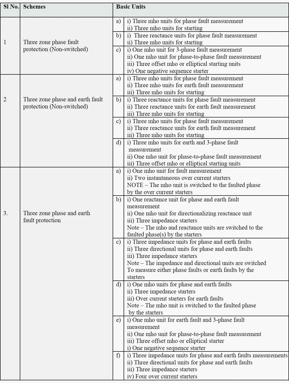
To cater for the economic and technical requirements of any particular network, a range of schemes is necessary from which a choice may be made. The schemes generally employed to meet the protection requirements of low, medium and high voltage networks may be classified into three main groups:
- Schemes designed for protection against phase faults only;
- Schemes designed for protection against all types of faults – phase and earth – using separate units for each type of fault (also referred to as non-switched schemes); and
- Schemes designed for protection against various type of faults using one set of units only but incorporating switching features (also referred to as switched schemes).
Table 1 – Typical distance protection schemes
Step Distance Schemes
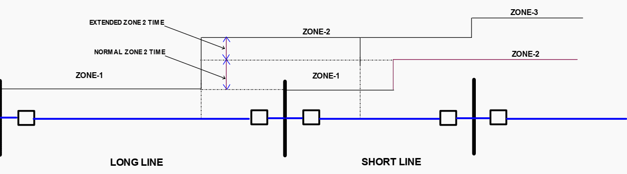
Step distance protection relays are those where pilot application is not used. Several zones are employed to protect a transmission line. Typical time distance characteristics for a three step relay is shown in Figure 6.

The first zone (zone 1) is instantaneous zone of protection and set to trip with no intentional time delay. Zone 1 is usually set for approximately 80% of the transmission line. This limitation is necessary to ensure ample margin against possible over reach due to current transients, current and voltage transformer errors and variation of line impedance.
The second zone (zone 2) is set to protect the line plus an adequate margin.
In special cases reach of zone 2 may be extended see Figure 7 for a short line where setting as high 200% can be helpful. Zone 2 relays are time delayed to co-ordinate relay at remote bus. Typical time delays are in order of 15 – 30 cycles.
Although zone 1 and zone 2 provide full protections to the transmission line, a third forward reaching zone 3 is employed as back up for zone 2 and may be employed as remote backup. This relay must be time delayed to coordinate with the remote zone 1and zone 2 relay.
Further discussion on time setting of zone 3 may be made to IEEE std. C-37113.
In order to detect faults in the second and third zones it is necessary to include starting relay sensitive enough to detect faults occurring beyond third zone under minimum generating condition, but capable of discrimination between this and normal load conditions at the end of the first section of line.
Understanding Line Distance protection (ANSI 21)
This video introduces transmission line protection (also called impedance protection, 21-element protection, or line distance protection).
Sources:
- Electrical transmission and distribution by ABB
- IEC-60255 (Part 1 to part 23) – Electrical relays
- IEEE std. C37. 102 – IEEE Guide for AC Generator Protection
- Siemens PTDEA Application of SIPROTEC protection relay
Related electrical guides & articles


Edvard Csanyi
Hi, I'm an electrical engineer, programmer and founder of EEP - Electrical Engineering Portal. I worked twelve years at Schneider Electric in the position of technical support for low- and medium-voltage projects and the design of busbar trunking systems.I'm highly specialized in the design of LV/MV switchgear and low-voltage, high-power busbar trunking (<6300A) in substations, commercial buildings and industry facilities. I'm also a professional in AutoCAD programming.
Profile: Edvard Csanyi

More information in protection relay.
I need more on transmission line protection
Thanks ever so much for your exceptional articles on power system protection.
I have decided to do my master in control engineering because I will like to proffer satisfactory and professional control and protection service services.
So I would like to have this article, very interesting.
However, thank you for sharing.
I kindly ask you to send me the pdf form of this subject asap, if possible. I would be very much grateful if you can do me a favor.
Thanks a lot and Best Regards.
Tayfun Konur / Sen. Elc. Power Engineer
do you have any vacancies just now