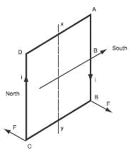
The operating principle of an asynchronous motor involves creating an induced current in a conductor when the latter cuts off the lines of force in a magnetic field, hence the name “induction motor”. The combined action of the induced current and the magnetic field exerts a driving force on the motor rotor.
Let’s take a shading ring ABCD in a magnetic field B, rotating round an axis xy (C Fig. 1). If, for instance, we turn the magnetic field clockwise, the shading ring undergoes a variable flux and an induced electromotive force is produced which generates an induced current (Faraday’s law).
According to Lenz’s law, the direction of the current is such that its electromagnetic action counters the cause that generated it.
Each conductor is therefore subject to a Lorentz force F in the opposite direction to its own movement in relation to the induction field.

An easy way to define the direction of force F for each conductor is to use the rule of three fingers of the right hand (action of the field on a current, – Fig. 2).
The thumb is set in the direction of the inductor field. The index gives the direction of the force. The middle finger is set in the direction of the induced current.
The shading ring is therefore subject to a torque which causes it to rotate in the same direction as the inductor field, called a rotating field. The shading ring rotates and the resulting electromotive torque balances the load torque.


