
Estimated Study Time: 22 minutes
GIS operation and maintenance
After its inception in the mid-1960s, GIS technology has become a remarkable success over a wide range of high voltage applications up to 800 kV. Reliable operation and compact size have been its main advantages over its conventional air-insulated counterparts. Despite a very high initial capital cost, these two advantages reflect in other multiple aspects like low maintenance, minimum footprint, enhanced safety, pleasing aesthetics, and so on.
 Secrets and warnings in operation and maintenance of a Gas Insulated Substation (GIS)
High Voltage Gas Insulated Substations (GIS) are one-time installations having a very long operating life with minimal maintenance, unlike Air Insulated Substations (AIS). However, being a complex and high-cost construction, the operation and maintenance of GIS is still an elusive topic that requires a closely coordinated plan and schedule based on the manuals and instructions of OEMs.
They draw a lot of similarities, as well as quite a few differences from their conventional counterpart, AIS.
In this article, we shall focus on operational and maintenance aspects that are unique to a GIS, skipping the general norms common to any high voltage substation.
- Typical layout design aspects
- Operational aspects
- Fault and troubleshooting
- Types and schedule of maintenance
1. Typical layout Design aspects
The requirement of client and design considerations lay the first foundation for the basic configuration of a substation, whether it be an AIS or a GIS. For a GIS, the design process takes a definitive shape with a detailed Single Line Diagram including some specific requirements.
For instance, the number and position of earthing switches. Based on the SLD, the designer can prepare an initial layout with proper consideration of available space, site condition- Indoor or outdoor, provision of incoming and outgoing feeders, interconnection with other components, selection of GIS type- fully encapsulated or hybrid, etc.
The flowchart below illustrates the process:
Figure 1 – Typical flowchart for GIS design and implementation
Specifics of layout design
Optimizing the GIS bays is very important to reduce the length of the bus duct, which otherwise comes with a hefty cost increment and might even degrade the system reliability.
The designer could incorporate various layout options like- single or three-phase encapsulations (based on voltage levels), horizontally or vertically aligned circuit breakers, horizontal or vertical bus ducts, single or multiline arrangement of components, etc.
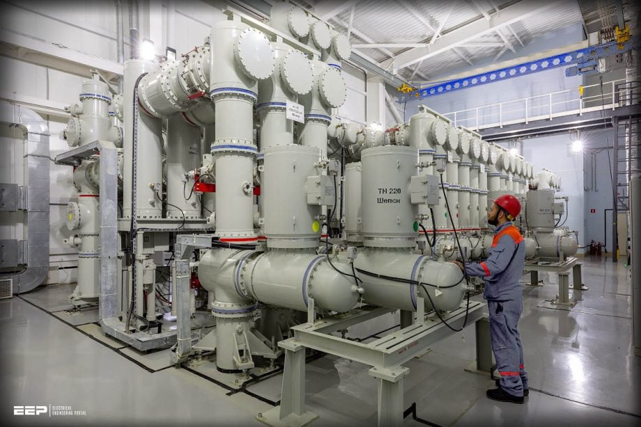
Figure 2 – An example of GIS layout in a substation

Go back to the Contents Table ↑
2.Operational aspect
Operating a GIS module could be a challenge for untrained operators because of completely encapsulated switchgear, measuring equipment, and conducting parts. Although the components and operations are principally similar to an AIS, the physical arrangement of those elements marks a notable difference.
The presence of metallic enclosure and unavailability of visible indication of component operations require getting used to. Furthermore, a GIS module requires stringent interlocking schemes between breakers, maintenance switches, and earthing switches to ensure safe operation and maintenance.
Related electrical guides & articles


Bishal Lamichhane
Electrical Engineer (B.E Electrical, M. Sc Engineering) with specialization in energy systems planning. Actively involved in design and supervision of LV/MV substations, power supply augmentations and electrification for utilities and bulk consumers like airports and commercial entities. An enthusiast and scholar of power systems analysis.Profile: Bishal Lamichhane
