
Fibre optic systems
In several previous articles I mentioned optical fibre in the context of substation automation, protection signaling, communication between electrical devices, LAN communications, etc. Now I will get into details of fibre optic basics, design, jointing/termination and installation.
 How optical communication cables work and how they differ from other cables
Let’s start the discussion following the contents.
- The basics of fibre optic systems
- What are optical fibres?
- Optical cable design
- Interconnections, jointing and termination
- Installation tips
1. The basics
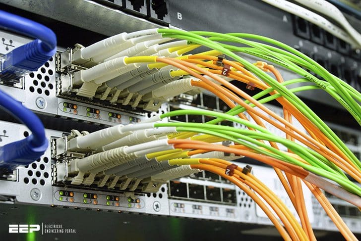
The fundamental components of a fibre optic system are shown in Figure 1. This system can be used for either analogue or digital transmissions, with a transmitter which converts electrical signals into optical signals.
The optical signals are launched through a joint into an optical fibre, usually incorporated into a cable. Light emitting from the fibre is converted back into its original electrical signal by the receiver.
2. What are Optical fibres?
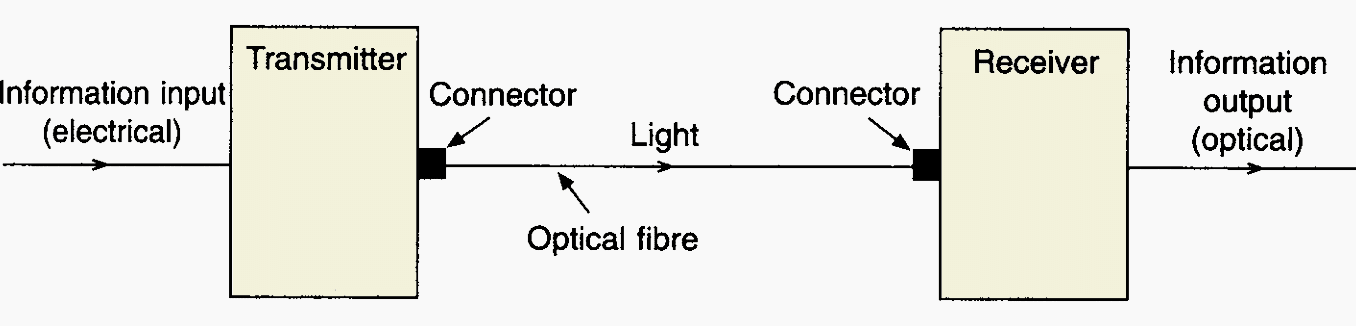
An optical fibre is a dielectric waveguide for the transmission of light, in the form of a thin filament of very transparent silica glass.
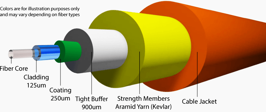
As shown in Figure 2, a typical fibre comprises a core, the cladding, a primary coating and sometimes a secondary coating or buffer. Within this basic construction, fibres are further categorized as multi-mode or single-mode fibres with a step or graded index.
In this type of fibre, the light rays can be envisaged as travelling along a zigzag path of straight lines, kept within the core by total reflection at the inner surface of the cladding.
Depending on the angle of the rays to the fibre axis, the path length will differ so that a narrow pulse of light entering the fibre will become broader as it travels. This sets a limit to the rate at which pulses can be transmitted without overlapping and hence a limit to the operating bandwidth.
To minimize this effect, which is known as mode dispersion, fibres have been developed in which the homogeneous core is replaced by one in which the refractive index varies progressively from a maximum at the centre to a lower value at the interface with the cladding.
Figure 3(b) shows such a graded index fibre, in which the rays no longer follow straight lines. When they approach the outer parts of the core, travelling temporarily faster, they are bent back towards the centre where they travel more slowly.
The mode dispersion of step index fibres has also been minimized by the development of single-mode fibres.
As shown in Figure 3(c), although it is a step index fibre, the core is so small (of the order of 8 µm in diameter) that only one mode can propagate.
Fibre manufacture involves drawing down a preform into a long thin filament. The preform comprises both core and cladding, and for graded index fibres, the core
contains many layers with dopants being used to achieve the varying refractive index.
Although the virgin fibre has a tensile strength comparable to that of steel, its strength is determined by its surface quality.
Typically the primary coating has a thickness of about 60 µm, and in some cases a further layer of material called the buffer is added to increase the mechanical protection.
Another type of optical fibre has a plastic construction, with either step or graded index cores. Although larger in size (up to 1.0 mm cladding diameter) and with higher transmission losses than glass fibres, plastic optical fibres have economic and handling advantages for short distance, low data rate communication systems.
3. Optical cable design
The basic aim of a transmission cable is to protect the transmission medium from its environment and the rigours of installation. Conventional cables with metallic conductors are designed to function effectively in a wide range of environments.
However, optical fibres differ significantly from copper wires to an extent that has a considerable bearing on cable designs and manufacturing techniques.
This means that cables must protect the fibre from strain during installation and service, and they must cater for longitudinal compression that occurs, for example with a change in cable temperature.
Fibre life in service is influenced by the presence of moisture as well as stress. The minute cracks which cover the surface of all fibres can grow if the fibre is stressed in the presence of water, so that the fibre could break after a number of years in service.
Cables must be able to provide a long service life in such environments as tightly packed ducts which are filled with water.
The initial application of optical cables was the trunk routes of large telecommunications networks, where cables were directly buried or laid in ducts in very long lengths, and successful cable designs evolved to take into account the constraints referred to earlier.
Further opportunities for optical cables are presented by installations in existing rights-of-way, such as sewers, gas pipes and water lines without the need for costly civil engineering works.
Nevertheless, many of the conventional approaches to cable design can be used for optical cables, with modification to take into account the optical and mechanical characteristics of fibres and their fracture mechanics.
Cables generally comprise several elements or individual transmission components, such as copper pairs, or one or more optical fibres. The different types of element used in optical cables are shown in Figure 4 above.
The primary-coated fibre can be protected by a buffer of one or more layers of plastic material as shown in Figure 4(a).
Typically for a two-layer buffer, the inner layer is of a soft material acting as a cushion with a hard outer layer for mechanical protection, the overall diameter being around 850 µm. In other cases, the buffer can be applied with a sliding fit to allow easy stripping over long lengths.
In ruggedized fibres further protection for a buffered fibre is provided by surrounding it with a layer of non-metallic synthetic yarns and an overall plastic sheath. This type of arrangement is shown in Figure 4(b).
When one or more fibres are run loosely inside a plastic tube, as shown in Figure 4(c), they can move freely and will automatically adjust to a position of minimum bending strain to prevent undue stress being applied when the cable is bent. If the fibre is slightly longer than the tube, a strain margin is achieved when the cable is stretched, say during installation, and for underground and duct cables the tube can be filled with a gel to prevent ingress of moisture.
Optical fibres can be assembled into a linear array as a ribbon, as shown in Figure 4(d). Up to 12 fibres may be bonded together in this way or further encapsulated if added protection is required.
In order to prevent undue cable elongation which could stress the fibres, optical cables generally incorporate a strength member. This may be a central steel wire or strand, or non-metallic fibreglass rods or synthetic yarns.
The strength member should be strong, light and usually flexible, although in some cases a stiff strength member can be used to prevent cable buckling which would induce microbending losses in the fibres.
Strength members are shown in the cable layouts in Figure 5(b) and (c). The strength member can be incorporated in a structural member which is used as a foundation for accommodating the cable elements.
An example is shown in Figure 5(c), where a plastic section with slots is extruded over the strength member with ribbons inserted into the slots to provide high fibre count cables.
A moisture barrier can be provided either by a continuous metal sheath or by a metallic tape with a longitudinal overlap, bonded to the sheath. Moisture barriers can be of aluminium, copper or steel and they may be flat or corrugated. In addition, other cable interstices may be filled with gel or water-swellable filaments to prevent the longitudinal ingress of moisture.
Although the same basic principles of cable construction are used, the wide range of applications result in a variety of cable designs, from simplex indoor patch cords to cables containing several thousand fibres for arduous environments, to suboceanic cables.
Figure 5 shows just a few examples.
4. Interconnections, jointing and termination
The satisfactory operation of a fibre optic system requires effective jointing and termination of the transmission medium in the form of fibre-to-fibre splices and fibre connections to repeaters and end equipment.
For all types of interconnection there is an insertion loss, which is caused by Fresnel reflection and by misalignment of the fibres. Fresnel reflection is caused by the changes in refractive index at the fibre–air–fibre interface (Figure 6), but it can be minimized by inserting into the air gap an index-matching fluid with the same refractive index as the core.
Misalignment losses arise from three main sources as shown in Figure 7. Interconnection designs aim to minimize these losses. End-face separation (Figure 7(a)) allows light from the launch fibre to spread so that only a fraction is captured by the receive fibre.
This should therefore be minimized.

Normally the fibre cladding is used as the reference surface for aligning fibres, and the fibre geometry is therefore important, even when claddings are perfectly aligned.
Angular misalignment can result in light entering the receive fibre at such an angle that it cannot be accepted.
It follows that very close tolerances are required for the geometry of the joint components and the fibres to be jointed, especially with single-mode fibres with core diameters of 8 µm and cladding diameters of 125 µm.
The main types of interconnections are fibre splices and demountable connectors.
Fibre splices
Fibre splices are permanent joints made between fibres or between fibres and device pigtails. They are made by fusion splicing or mechanical alignment. In fusion splicing, prepared fibres are brought together, aligned and welded by local heating combined with axial pressure.
Sophisticated portable equipment is used for fusion splicing in the field. This accurately aligns the fibres by local light injection and it carries out the electric arc welding process automatically.
Nevertheless, a level of skill is required in the preparation of the fibres, stripping the buffers and coatings and cleaving the fibres to achieve a proper end face.
There are a number of mechanical techniques for splicing fibres which involve fibre alignment by close tolerance tubes, ferrules and v-grooves, and fixing by crimps, glues or resins. Both fusion and mechanical splicing techniques have been developed to allow simultaneous splicing of fibres which are particularly suitable for fibre ribbons.
The enclosure must also terminate the cables and organize the fibres and splices, and cassettes are often used where several hundred splices are to be accommodated.
Demountable connectors
Demountable connectors provide system flexibility, particularly at and within the transmission equipment and distribution panels, and they are widely used on patch cords in certain data systems.
As with splices, the connector must minimize Fresnel and misalignment loss, but it must also allow for repeated connection and disconnection, it must protect the fibre end face and it must cater for mechanical stress, such as tension, torsion and bending.
Demountable connectors have also been developed for multiple-fibre simultaneous connection, with array designs being particularly suitable for fibre ribbons.
For connector-intensive systems, such as office data systems, use is made of factory-predetermined cables and patch cords to reduce the need for on-site termination.
5. Installation tips
Optical fibre cables are designed so that normal installation practices and equipment can be used wherever possible.
As they generally have a lower strain limit than metallic cables special care may be needed in certain circumstances and manufacturer’s recommendations regarding tensile loads and bending radius should be followed.
Special care may be required in the following circumstances:
- Because of their light weight, optical cables can be installed in greater lengths than metallic cables. For long underground ducts access may be needed at intermediate points for additional winching effort and space should be allowed for larger cable deployment.
- Mechanical fuses and controlled winching may be necessary to ensure that the rated tensile load is not exceeded.
- Guiding equipment may be necessary to avoid subjecting optical cables to unacceptable bending stresses, particularly when the cable is also under tension.
- When installing cables in trenches the footing should be free from stones. These could cause microbending losses.
- In buildings, and particularly in risers, cleats and fixings should not be overtightened, or appropriate designs should be used to prevent compression and the resulting microbending losses.
- Indoor cable routes should provide turning points if a large number of bends is involved. Routes should be as straight as possible.
- Excess lengths for jointing and testing of optical cables are normally greater that those required for metallic cables.
- Where non-metallic optical cables are buried, consideration of the subsequent location may be necessary. Marker posts and the incorporation of a location wire may be advisable.
It results in low initial capital costs and provides for the distribution of subsequent costs. Initially developed by British Telecom, the network infrastructure is created by the most appropriate cabling method, being one or a group of empty plastic tubes.
As and when circuit provision is required, one or more fibres can be blown by compressed air into the tubes. Individual tubes can, by means of connectors, be extended within buildings up to the fibre terminating equipment.
For installation it is necessary to follow the instructions provided by the supplier, taking into account the requirements for the use of portable electrical equipment and compressed air, and the handling, cutting and disposal of optical fibres.
A novel variation of this system is a data cable used for structural wiring systems.
Reference // Electrical Power Engineer’s Handbook by D.F. Warne (Purchase hardcopy from Amazon)


i need more books for telecommunication engineering
Beautiful presentation of important basics, simple and easy to understand.