
Estimated Study Time: 16 minutes
Switchgear installations
The arrangement of outdoor switchgear layouts and installations is mostly influenced by economic considerations, in particular adaptation to the space available and the operational requirements of reliability and ease of supervision.
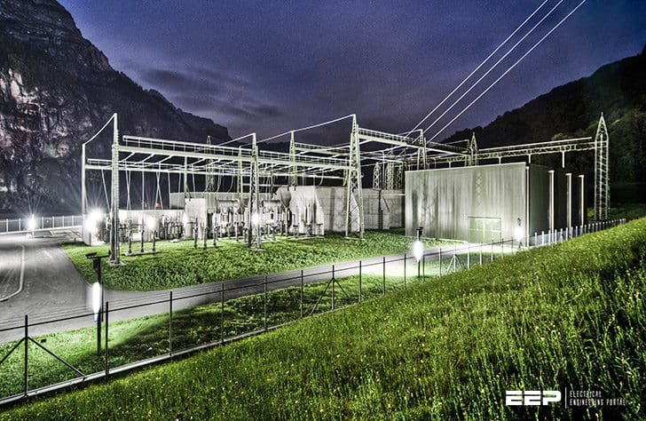 The Most Used Outdoor Switchyard Layouts You Should Know About (photo credit: ABB)
1. Switchyard layout in general
To meet above conditions, various layouts (see Table 1) have evolved for the circuit configurations.
Many electric utilities have a preference for certain arrangements which they have adopted as standard. The spacing of the branches is determined by the switchyard configuration. A span length of 50 m is economical for guyed wire (strain) busbars. The number and design of portal structures is governed by the overall length of the installation.
In 123 kV stations, the tubular busbars are supported at each alternate bay, but at each bay with higher voltages.
The overhead lines leading from the transformer stations are generally also used for power-line carrier telephony. The necessary equipment (line trap, capacitor) is incorporated in the outgoing overhead lines as shown in Figure 1.

Where:
- Circuit-breaker
- Feeder disconnector
- Current transformer
- Inductive voltage transformer
- Capacitive voltage transformer
- Capacitor
- Line trap
Points in favour of rotary and vertical-break disconnectors are their mechanical simplicity and the fact that they are easier to position as feeder disconnectors.
The single-column disconnector makes for a simple station layout owing to its isolating distance between the two line levels. It saves some 20% of the ground area needed for two-column disconnectors.
Table 1 – Outdoor switchyard configurations, preferred application
| Layout | ≤ 145 kV | 245 kV | 420 kV | ≥ 525 kV |
| Low rise (classical layout) | x | x | ||
| In-line layout | x | |||
| Transverse layout | x | x | ||
| High-rise layout | x | |||
| Diagonal layout | x | x | ||
| 1½-breaker layout | x | x | x |
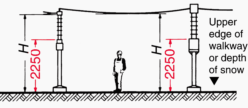
Each branch (bay) consists of the circuit-breaker with its disconnectors, instrument transformers and control cubicle. The apparatus is best placed at a height such that no fencing is needed.
Here, it must be noted that according to DIN VDE 0101 (see figure), the height to the top edge of the earthed insulator base must be at least 2250 mm. The high-voltage apparatus is generally mounted directly on equipment support structures.
2. Selected examples of switchyard layouts
2.1. Low rise (classical layout)
With the low-rise (classical) layout (Figure 2), the busbar disconnectors are arranged side by side in line with the feeder. The busbars are strung above these in a second level, and in a third plane are the branch lines, with connections to the circuit-breaker.
The classical layout is also used for stations employing the 2-breaker method.
Where:
- Busbar system I
- Busbar system II
- Busbar disconnector
- Circuit-breaker
- Current transformer
- Voltage transformer
- Feeder disconnector
- Surge arrester
- T Bay width
- T1 Width initial bay
- T2 Width final bay at busbar dead-end
2.2. In-line layout
An in-line layout with tubular busbars is shown in Figure 3. It is employed with busbar current ratings of more than 3000 A. The poles of the busbar disconnectors stand in line with the busbars. Portals are needed only for the outgoing overhead lines.
In stations including a bypass bus, the layout chosen for the bypass bus and its disconnectors is the same as for the busbars. In stations with feeders going out on both sides, the bypass bus must be U-shaped so that all branches can be connected to it.
Where:
- Busbar system I
- Busbar system ll
- Busbar disconnector
- Circuit-breaker
- Current transformer
- Voltage transformer
- Feeder disconnector
- Surge arrester
- T Bay width,
- T1 Width initial bay
- T2 Width final bay
2.3. Transverse layout
With the transverse layout, the poles of the busbar disconnectors are in a row at right angles to the busbar, see Figure 4. With this arrangement too, the busbars can be of wire or tube. The outgoing lines are strung over the top and fixed to strain portals.
Though the bay width is small, this arrangement results in a large depth of installation.

Where:
- Busbar system I
- Busbar system ll
- Busbar disconnector
- Circuit-breaker
- Current transformer
- Voltage transformer
- Feeder disconnector
- Surge arrester
- T Bay width
- T1 Width initial bay
- T2 Width final bay
Special layouts
Arrangements with draw-out breakers save a great deal of space, as the draw-out circuit-breaker does away with the need for disconnectors. The outgoing line simply includes an earthing switch. This configuration is used for stations with single busbars.
2.4. High-rise layout
Load-centre substations with one or two power transformers are usually in the form of simplified transformer stations. In Figure 5, two incoming overhead lines connect to two transformers (H-connection).
This gives rise to two busbar sections joined via two sectionalizers (two disconnectors in series).
In this way, each part of the installation can be isolated for maintenance purposes. The bus sections can be operated separately or crosswise, ensuring great reliability and security of supply.

Where:
- Busbars
- Busbar disconnector
- Circuitbreaker
- Current transformer
- Voltage transformer
- Feeder disconnector
- Surge arrester
2.5. Diagonal layout
With this arrangement, the (single-column) busbar disconnectors are arranged diagonally with reference to the busbars. It is commonly used for 245 kV and 420 kV
stations. A distinction is made between two versions, depending on the position (level) of the busbars:
- Busbars above
- Busbars below
2.5.1. Diagonal “busbars above” layout
The advantage of this layout (Figure 6) is that when a feeder is disconnected, the busbar disconnectors are also disconnected and are thus accessible.
Figure 6 shows a 420 kV station in a diagonal layout and using tubes. The tubes are in lengths of one bay and mounted on the post insulators with a fixed point in the middle and sliding supports at either end.
The busbars can be welded together over several bays up to about 120 m.

Where:
- Busbar system I
- Busbar system II
- Busbar disconnector
- Circuit-breaker
- Current transformer
- Feeder disconnector
- Line trap
- Capacitive voltage transformer
- T Bay width
- T1 Width initial bay
- T2 Width final bay
2.5.2. Diagonal “busbars below” layout
With this arrangement, the busbars are mounted on the disconnectors with the outgoing lines strung at right angles to them. At their points of intersection, single-column disconnectors maintain the connection with their vertical isolating distance.
The circuit-breakers for all outgoing lines are on the same side of the busbars so that only one path is needed for transport and operation. The lines to the transformers lie in a third plane.

Where:
- Busbar system I
- Busbar system II
- Busbar disconnector
- Circuit-breaker
- Current transformer
- Feeder disconnector
- Line trap
- Capacitive voltage transformer
- T Bay width
- T1 Width initial bay
- T2 Width final bay with busbar dead-end
2.5.3. Diagonal layout with bypass bus, single-row arrangement
The 420 kV switchyards of the German transmission grid are of the diagonal type. To meet the stringent demands of station operation and reliability, double or triple busbars with sectionalizing and an additional bypass bus are customary.
Tube-type busbars are preferred. These can handle high current ratings and high short-circuit stresses.
Single-column isolators are used for the busbars and the bypass bus (see Figure 8).

Where:
- Busbar system I
- Busbar system II
- Busbar system III
- Bypass bus
- Busbar disconnector
- Circuit-breaker
- Feeder disconnector
- Bypass disconnector
- Current transformer
- Voltage transformer
- a and b Ties for busbars 1, 2 and 3 and bypass bus 4
- c Outgoing line
2.6. 1½-breaker layout
The 1½-breaker configuration is used mainly in countries outside Europe. It is employed for all voltages above 110 kV, but predominantly in the very high voltage
range.
The branches are always arranged in two rows. The disconnectors used are of the pantograph and two-column vertical-break types. Vertical-break disconnectors are employed in the outgoing line.
Figure 9 shows a section through one bay of a 525 kV station, the busbars are of wire.
This arrangement allows the station to be operated on the ring bus principle while construction is still in progress, and before all the switchgear apparatus has been installed.
Where:
- Busbar system I
- Busbar system II
- Busbar disconnector
- Circuit-breaker
- Current transformer
- Voltage transformer
- Feeder disconnector
- Branch disconnector
- Surge arrester
- Line trap
- Transformer
3. Comparison of different layouts
Table 2 compares different layouts of 123-kV outdoor switchyards as regards area, foundations (volume) and steelwork (weight) for one line branch and one transformer branch with double busbar, assuming a total size of the substation of 5 bays.
Table 2 – Comparison of different layouts for 123 kV
| Type of branch (bay) | Overhead line | Transformer | ||||
| Type of layout | Area | Foundations (volume) | Steel-work | Area | Foundations (volume) | Steel-work except cable gantry on LV side |
| In-line (tubular busbars) | 225 m2 100 % | 23.3 m3 100 % | 6.6 t 100 % | 193 m2 100 % | 52.3 m3 100 % | 4.3 t 100 % |
| Transverse (tubular busbars) | 282 m2 125 % | 27.2 m3 117 % | 7.8 t 118 % | 302 m2 156 % | 78.4 m3 150 % | 9.6 t 223 % |
| Low-rise (classical, wire busbars) | 192 m2 86 % | 33.9 m3 145 % | 8.4 t 127 % | 201 m2 104 % | 81.3 m3 155 % | 8.8 t 205 % |
Table 3 compares different layouts of 245-kV outdoor switchyards as regards area, foundations (volume) and steelwork (weight) for one line branch and one transformer branch with double busbar and bypass bus or 1½-breaker layout.
Table 3 – Comparison of different layouts for 245 kV
| Type of branch (bay) | Overhead line | Transformer | ||||
| Type of layout | Area | Foundations (volume) | Steel-work | Area | Foundations (volume) | Steel-work except cable gantry on LV side |
| In-line (tubular busbars) | 323 m2 100 % | 28 m3 100 % | 7.9 t 100 % | 344 m2 100 % | 63.2 m3 100 % | 7.0 t 100 % |
| Transverse (tubular busbars) | 413 m2 128 % | 31.9 m3 114 % | 9.1 t 115 % | 433 m2 126 % | 69.2 m3 110 % | 9.4 t 134 % |
| Low-rise (classical, wire busbars) | 324 m2 100 % | 38.6 m3 138 % | 10.4 t 132 % | 369 m2 107 % | 83.1 m3 131 % | 12.5 t 179 % |
| 1½-breaker (tubular busbars) | 267 m2 83 % | 27.4 m3 98 % | 8.1 t 103 % | 301 m2 88 % | 47.7 m3 76 % | 8.5 t 121 % |
Reference // ABB Switchgear Manual
Related electrical guides & articles


Edvard Csanyi
Hi, I'm an electrical engineer, programmer and founder of EEP - Electrical Engineering Portal. I worked twelve years at Schneider Electric in the position of technical support for low- and medium-voltage projects and the design of busbar trunking systems.I'm highly specialized in the design of LV/MV switchgear and low-voltage, high-power busbar trunking (<6300A) in substations, commercial buildings and industry facilities. I'm also a professional in AutoCAD programming.
Profile: Edvard Csanyi

Dear Sir,
Would You please like to share with us the latest edition of ABB Switchgear Manual.
I have 10th Edition which is very old and I couldn’t find the new edition here (EEP). Please guide me. Waiting for Your kind help and support. Please let me know via E-mail.
It’s a great and wonderful website and an excellent effort of Yours.
Thanks and kind regards
Hi Sir Edvard how can i get an soft copy pdf file of this topic?
I just wanted to ask if EEP have any training school for electrical certified engineer
Articles are exhaustive and explained in simple language . I love the portal.
i’m interesting in power system optimization control and operation
I need furthering my electric knowledges especially on substation and high voltage distribution where can go ?
I’ve paid for premium membership, but I cannot download technical articles.
May you help me?
Hi Bartien, I sent you an email with instructions.
Edvard