
Estimated Study Time: 16 minutes
Essential protection principles
The aim of this technical article is to cover the most important principles of four fundamental relay protections: overcurrent, directional overcurrent, distance and differential for transmission lines, power transformers and busbars.
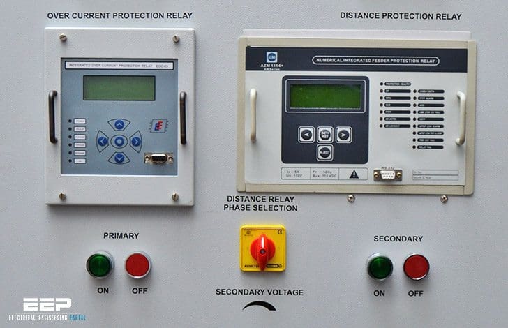 Fundamental overcurrent, distance and differential protection principles (photo credit: Power Research & Development Consultants Pvt. Ltd)
- Principle of overcurrent protection
- Principle of directional overcurrent protection
- Principle of distance protection
- Principle of differential protection
For simplicity in explaining the key ideas, we consider three phase bolted faults.
1. Overcurrent protection
Transmission and distribution systems are susceptible to overcurrent flow within their components. In an electric power system, overcurrent refers to a condition when the electric current surpasses the intended level in a conductor, resulting in excessive heat generation and the potential for fire or equipment damage. Potential sources of overcurrent encompass short circuits, high load, transformer inrush current, motor initiation, design flaws, or ground faults.
Consequently, under standard system conditions, various strategies including demand-side management, load shedding, and gentle motor starting may be utilized to prevent overloads.
Moreover, distribution systems are outfitted with protective relays that activate mechanisms to ensure switching equipment responds solely to atypical system conditions.
This scheme is based on the intuition that, faults typically short circuits, lead to currents much above the load current. We can call them as overcurrents. Over current relaying and fuse protection uses the principle that when the current exceeds a predetermined value, it indicates presence of a fault (short circuit).
This protection scheme finds usage in radial distribution systems with a single source. It is quite simple to implement.
Figure 1 – Radial distribution system
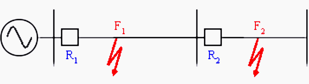
Figure 1 shows a radial distribution system with a single source. The fault current is fed from only one end of the feeder.
For this system it can be observed that:
- To relay R1, both downstream faults F1 and F2 are visible i.e. IF1 as well as IF2 pass through CT of R1.
- To relay R2, fault F1, an upstream fault is not seen, only F2 is seen. This is because no component of IF1 passes through CT of R2. Thus, selectivity is achieved naturally.Relaying decision is based solely on the magnitude of fault current. Such a protection scheme is said to be non-directional.
Go back to protection principles ↑
2. Directional overcurrent protection
Ground distance and directional ground overcurrent relays are frequently employed to identify ground faults in transmission lines. Ground distance relays may lack sufficient sensitivity to identify all impedance-limited ground faults due to the limitations of the distance element characteristic on resistive reach.
Ground overcurrent relays are more adept at detecting these faults due to their superior sensitivity to resistance-limited faults.
The nature of grounding, system characteristics, and individual fault impedance dictate the severity of ground faults. Faults with considerable impedance exhibit a comparatively modest current magnitude compared to faults lacking significant impedance. Such faults can challenge distance relays because to their sensitivity related to the angle of the line characteristic impedance.
In contrast, there can be situations where for the purpose of selectivity, phase angle information (always relative to a reference phasor) may be required. Figure 2 shows such a case for a radial system with source at both ends. Consequently, fault is fed from both the ends of the feeder.
To interrupt the fault current, relays at both ends of the feeder are required.
Figure 2 – Radial system with source at both ends
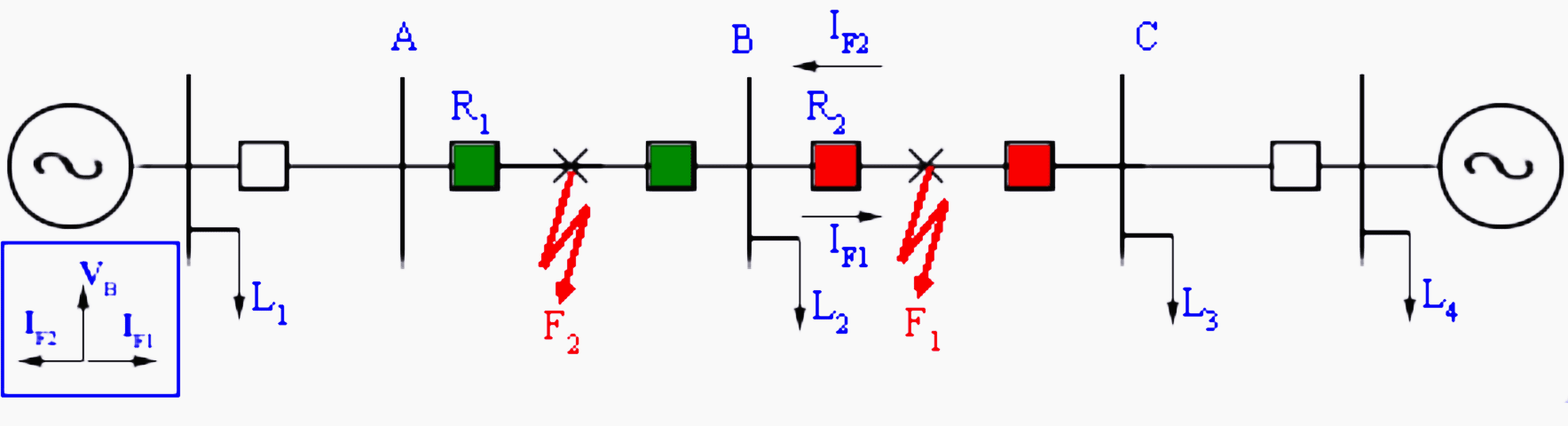
In this case, from the magnitude of the current seen by the relay R2, it is not possible to distinguish whether the fault is in the section AB or BC. Since faults in section AB are not in its jurisdiction, it should not trip.
Go back to protection principles ↑
3. Distance protection
Distance relaying should be implemented when overcurrent relaying is insufficiently fast or lacks selectivity. Distance relays are typically employed for primary and backup protection against phase faults on subtransmission lines, as well as on transmission lines where high-speed automated reclosing is unnecessary for stability and where a brief delay for end-zone faults is acceptable
Overcurrent relays have traditionally been employed for primary and backup protection against ground faults; however, there is an increasing inclination towards utilizing distance relays for ground fault protection as well.
Single-step distance relays are employed for phase-fault backup protection at generator terminals. Single-step distance relays may be beneficial for backup protection at power transformer banks; however, current practice typically use inverse-time overcurrent relays for this purpose.
Consider a simple radial system, which is fed from a single source. Let us measure the apparent impedance (V/I) at the sending end.
For the unloaded system, I = 0, and the apparent impedance seen by the relay is infinite. As the system is loaded, the apparent impedance reduces to some finite value (ZL+Zline) where ZL is the load impedance and Zline is the line impedance. In presence of a fault at a per-unit distance ‘m’, the impedance seen by the relay drops to a mZline as shown in figure 3 below.
Figure 3 – Fault in transmission line
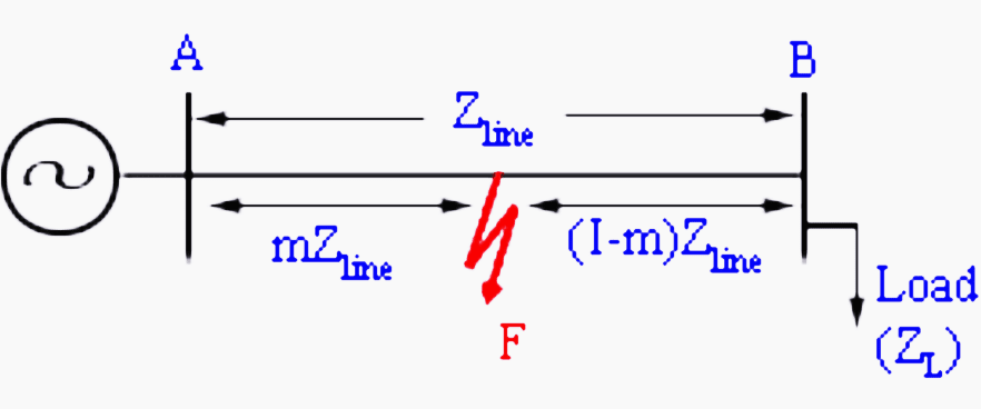
The basic principle of distance relay is that the apparent impedance seen by the relay, which is defined as the ratio of phase voltage to line current of a transmission line (Zapp), reduces drastically in the presence of a line fault. A distance relay compares this ratio with the positive sequence impedance (Z1) of the transmission line. If the fraction Zapp/Z1 is less than unity, it indicates a fault. This ratio also indicates the distance of the fault from the relay.
However, if only magnitude information is used, non-directional impedance relay results. Figures 4 and 5 shows a characteristic of an impedance relay and ‘mho relay’ both belonging to this class.
Figures 4, 5 – Figure 4 (left) – Impedance relay; Figure 5 (right) – Mho relay
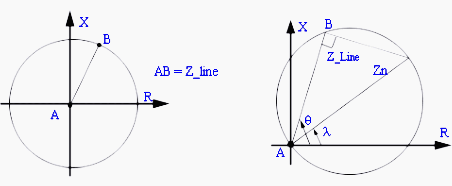
The impedance relay trips if the magnitude of the impedance is within the circular region. Since, the circle spans all the quadrants, it leads to non-directional protection scheme. In contrast, the mho relay which covers primarily the first quadrant is directional in nature.
Thus, the trip law for the impedance relay can be written as follows:
|Zapp| = |VR| / |IR| < |Zset|
then trip; else restrain.
While impedance relay has only one design parameter, Zset; ‘mho relay’ has two design parameters Zn, λ. The trip law for mho relay is given by if:
|Zapp| < |Zn| cos (θ – λ)
then trip; else restrain.
Go back to protection principles ↑
4. Principle of differential protection
Differential protection is based on the fact that any fault within an electrical equipment would cause the current entering it, to be different, from the current leaving it. Thus by comparing the two currents either in magnitude or in phase or both we can determine a fault and issue a trip decision if the difference exceeds a predetermined set value.
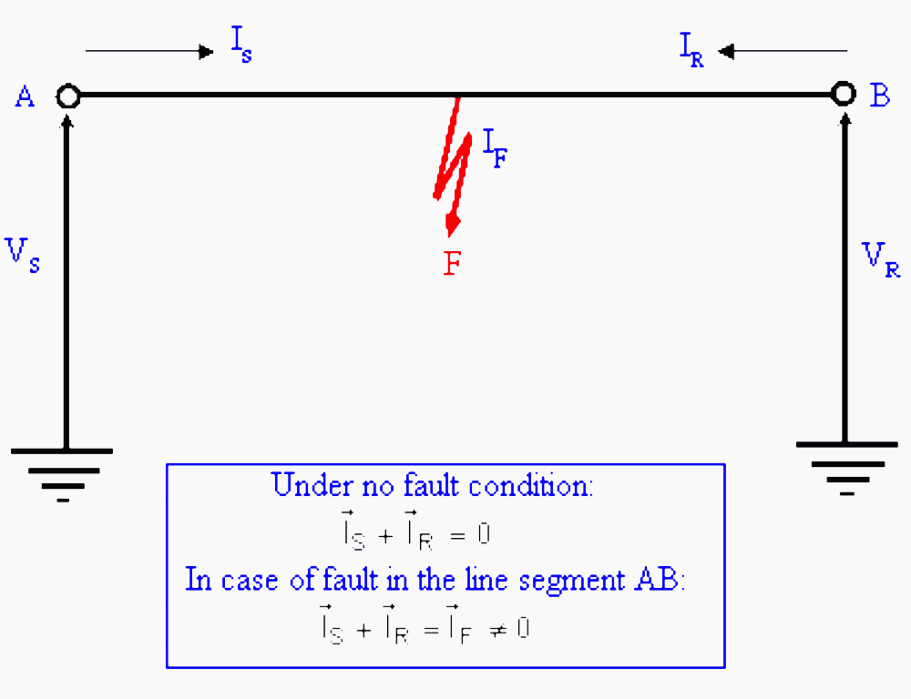
Figure 6 – Differential protection of short transmission line
Go back to protection principles ↑
4.1 Differential protection for transmission line
Figure 6 shows a short transmission line in which shunt charging can be neglected. Then under no fault condition, phasor sum of currents entering the device is zero i.e.
IS + IR = 0
Thus, we can say that differential current under no fault condition is zero. However in case of fault in the line segment AB, we get:
IS + IR = IF ≠ 0
i.e. differential current in presence of fault is non-zero.
In case of transmission line, implementation of differential protection requires a communication channel to transmit current values to the other end. It can be used for short feeders and a specific implementation is known as pilot wire protection. Differential protection tends to be extremely accurate. Its zone is clearly demarcated by the CTs which provide the boundary.
Differential protection can be used for tapped lines (multiterminal lines) where boundary conditions are defined as follows:
Figure 7 – Differential protection for tapped transmission line
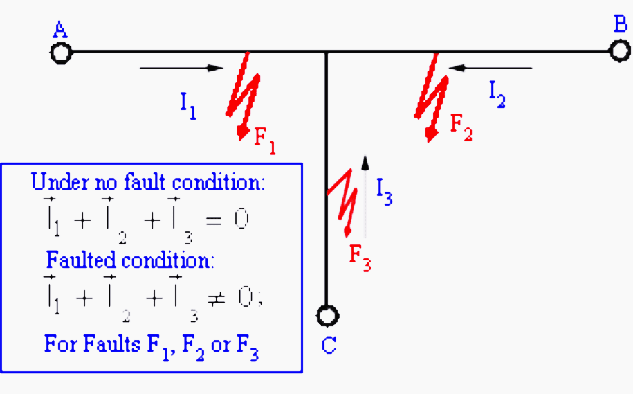
Under no fault condition:
I1 + I2 + I3 = 0
Faulted condition:
I1 + I2 + I3 ≠ 0
Go back to protection principles ↑
4.2 Differential protection for transformer
Differential protection for detecting faults is an attractive option when both ends of the apparatus are physically located near each other. e.g. on a transformer, a generator or a bus bar.
Consider an ideal transformer with the CT connections, as shown in Figure 8.
Figure 8 – Differential protection for transformer
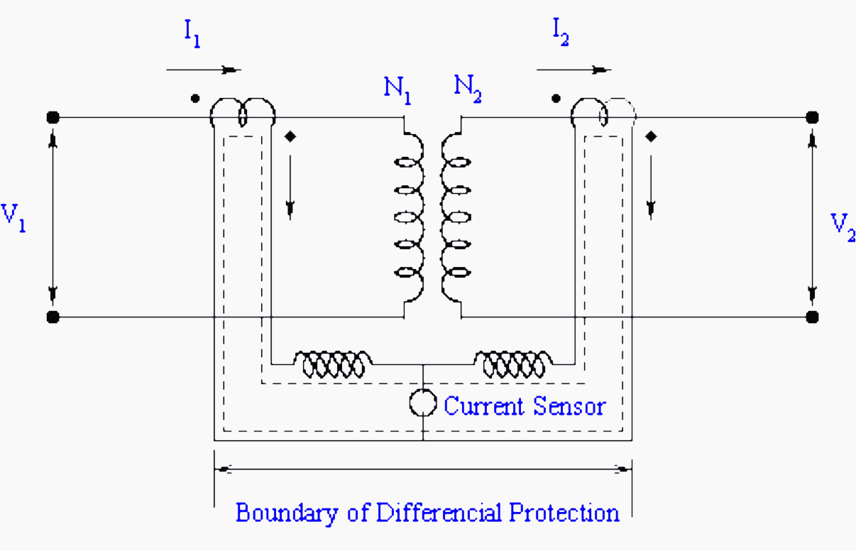
To illustrate the principle let us consider that current rating of primary winding is 100A and secondary winding is 1000A. Then if we use 100:5 and 1000:5 CT on the primary and secondary winding, then under normal (no fault) operating conditions the scaled CT currents will match in magnitudes. By connections the primary and secondary CTs with due care to the dots (polarity markings), a circulating current can be set up as shown by dotted line.
Now if an internal fault occurs within the device like interturn short etc., then the normal mmf balance is upset i.e. N1I1 ≠ N2I2. Under this condition, the CT secondary currents of primary and secondary side CTs will not match. The resulting differential current will flow through overcurrent relay. If the pick up setting of overcurrent relay is close to zero, it will immediately pick up and initiate the trip decision.
In practice, the transformer is not ideal. Consequently, even if I2=0, I1≠0, it is the magnetization current or (no load) current. Thus, a differential current always flows through the overcurrent relay.
Therefore overcurrent relay pick up is adjusted above the no load current value. Consequently, minute faults below no load current value cannot be detected. This compromises sensitivity.
Go back to protection principles ↑
4.3 Differential protection for busbar
Ideally, differential protection is the solution for the busbar protection. Figure 9 illustrates the basic idea. If the fault is external to the bus, it can be seen that algebraic sum of the currents entering the bus is zero.
IA + IB + IC + ID + IE = 0
Figure 9 – Differential protection for busbar
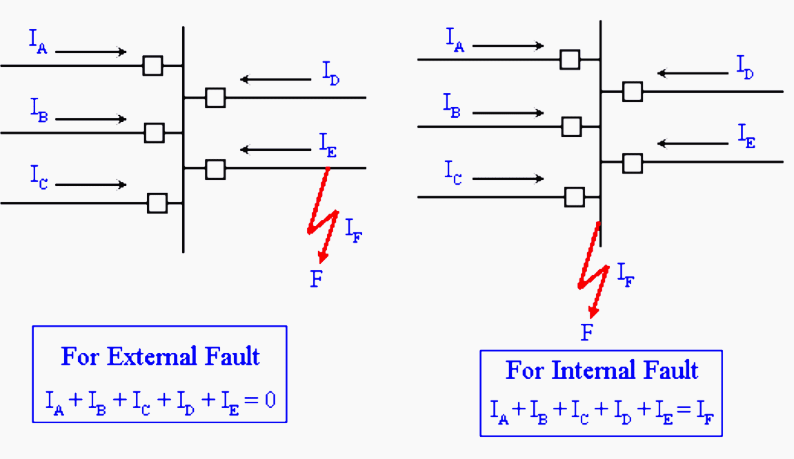
On the other hand, if fault is on the bus (internal fault), this sum is not zero.
IA + IB + IC + ID + IE = IF
Thus, differential protection can be used to protect a bus.
Go back to protection principles ↑
Reference: Fundamentals of Power System Protection – Extract from IIT Bombay NPTEL
Related electrical guides & articles


Edvard Csanyi
Hi, I'm an electrical engineer, programmer and founder of EEP - Electrical Engineering Portal. I worked twelve years at Schneider Electric in the position of technical support for low- and medium-voltage projects and the design of busbar trunking systems.I'm highly specialized in the design of LV/MV switchgear and low-voltage, high-power busbar trunking (<6300A) in substations, commercial buildings and industry facilities. I'm also a professional in AutoCAD programming.
Profile: Edvard Csanyi

Gone through the article and like it
Good night
I’m interested in the solution
What is best probable threshold or parameter setting calculation of medium voltage over head radial feeder to implement in non direction over current relay of 46 BC (Broken conductor feature).
Please send me details Differential relay setting calculation. Considering CT saturation condition, sample calculation for metrosil resistance value setting calculation
Dear Mr.Csanyi
In an engineering exam I had a question which addition to CT accuracy class C800 and CT ratio 1200/5, gave differential scheme ratio 900/5, which I never haired about, would you please advice me when we have CT ratio , what it means differential scheme ratio ?
Thank you so much for this great articles. So educative
I need better understanding/explanation on the subject matter below,
I work as a plant engineer in a power plant,
One of the 1.5MW gas engine do show this fault alarm “differential current” the p.f goes as low as 0.22 and then shutdown.
I am still reading up some materials that explained this
However,your knowledge as an expatriate can help me a great deal
Thanks
Many thanks about every golden information in this Great site
Keep me in touch if any ?
Regards.
Good Morning Mr. Edward !
Your posts are always found very useful for understanding.
Good afternoon Mr Edvard Csanyi
Salutes from Venezuela. About this post, I would like to ask you three things, exclusively for the distance protection. At the end of this principle it shown an equation, what is or what does mean Zset, Vr and Ir?.
Second question is, what is or what does mean Zn?
Finally, my third question is Where do I get the value of the torque angle?
Thanks in advance for your time.
Kind Regards
DATE: 26-DEC.-2016
INDEED, WITH THE ABOVE PRESENTATIONS OF TYPICAL APPLICATION CONFIGURATIONS OF PROTECTION RELAYING FOR ELECTRICAL POWER SYSTEM DISTRIBUTIONS, THE INSTALLED PROTECTION RELAY NEAREST THE FAULT LOCATION MUST SEE THE FAULT AND DETECT IT FIRST AND THE PICK-UP SETTING OF THIS RELAY SHOULD BE AT THE MINIMUM MAGNITUDE OF THE FAULT CURRENT OTHERWISE SETTING IT A HIGHER VALE NEAR THE MAX.FAULT WILL EXPOSE THE ELECTRICAL CIRCUIT TO THE EFFECT OF SHORT CIRCUIT THEREBY LETTING THROUGH THE CURRENT TO PASS THRU INCREASING THE TEMPERATURE DUE TO THERMAL AND MAGNETIC FORCE EFFECT OF THE FAULT WITHOUT INTERRUPTING THE FLOW IMMEDIATELY WHICH THEREFORE IS NOT A GOOD DESIGN AND IMPLEMENTATION OF PROTECTION.