Introduction to the designing principles
When designing an overhead transmission line, we should pay attention to ensure that the tension force does not exceed, in any case, the limit of the mechanical strength of the conductor.

The maximum stress occurs at the lower temperature,when the line is subjected to contraction, and a possible ice coating. Moreover, it should be considered that can simultaneously be and wind pressure on the line. To address these conditions, a requirement, is knowledge of the arrow of the conductor.
1. Static vision of the transmission line
Even:
l = span length in m (distance between two support points).
L = conductor length in m, corresponding to the opening l.
w = conductor weight in Kpper meter.
T = tensile strength of the transmission line, in Kp.
D = maximum arrow, in m.

2. Transmission line coated with ice & under the effect of wind
Even:
d = conductor diameter in cm.
i = radial ice thickness in cm.
wi= ice weight per meter.
P = wind pressure at speed of 80 km/hr.
W = resultant force (weight and wind pressure).

The vertical component of the arrow:
![]()
3. Calculation of the arrow (transmission line construction)
We accept as unfavorable conditions the following:
- Ambient temperature -10°C
- Radial ice coating 1 cm
- Wind speed 80 km/hr
With these conditions, we choose 2nd degree safety factor, so that the tension force should not exceed half the breaking load of the conductor.
According to Rapson:

when:
T = tensile strength during the construction, in Kp (is considered constant along the transmission line).
A = conductor cross section, in cm2
E = yield strength factor, in Kp/cm2
α = expansion factor per °C.
t = ambient temperature above -10°C.
Tc = tensile strength in adverse conditions, in Kp (Tc obtained half of the breaking load).
By solving the above formula, we obtain the value of T. Then, the arrow, during the construction, is:
![]()
4. Transmission line based on different levels
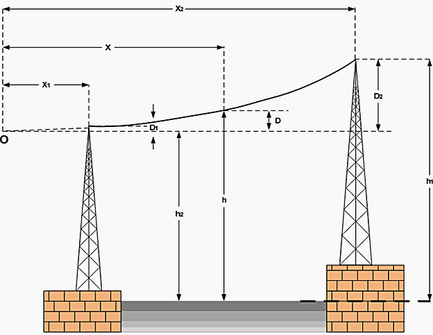
Consider “O” the imaginary lowest point of the transmission line.
x1 = is the horizontal distance between the lowest support point and the “O”.
x2 = is the horizontal distance between the highest support point and the “O”.
D1 = is the imaginary arrow from the lowest support point.
D2 = is the imaginary arrow from the highest support point.
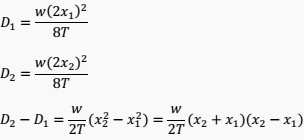
With these data, we have:

We observe that:

From the above, we have:

With the values of x1, x2, the arrows D1, D2 can be calculated, as well as the height of any point on the transmission line from the ground.
Example //
An overhead transmission line crosses a river and it is based on the two banks by two towers at height h1=91.4m and h2=45.7m above the water surface. The horizontal distance between the towers is 335.3 m. The maximum tensile force is T = 1932.3 Kp and the weight of the conductor is w = 0.884Kp/m.
Determine the height “h” of the line over the water, midway between the two towers.
Consider “O” the imaginary lowest point of the transmission line and D1, D2 the arrows from the lower and the tallest tower respectively.


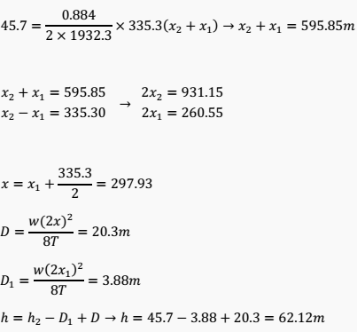
However:
![]()
Therefore:

Reference:
Vasilios N. Xanthos – Generation, Transmission, Distribution, Measurement and saving of Electrical Energy


Kp? I think you mean kP?