
Estimated Study Time: 12 minutes
CTs and VTs measures & recommendations
The installations wherein CTs and VTs are mounted to measure the normal and abnormal values of current and voltage, have many variations in key system parameters, including voltage class, insulation and short-circuit level, earthing type, rated current and burden, accuracy, ALF and size/design requirements, protection schemes, etc.
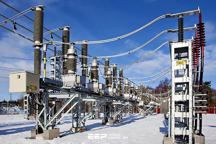 How not to overspecify high voltage CTs and VTs (photo credit: Siemens)
This leads to the use of numerous varieties of CTs and VTs. It is possible that even a frequent user of CTs may not come across two identical CTs over a period of many years. It is this limitation which makes it difficult to standardise CT and VT specifications, thereby resulting in seemingly endless lists.
Part of the problem arises due to the tendency of the user to over-specify his requirement just ‘to be on the safe side’ thereby resulting in avoidable extra costs.
1. Recommendations for Standardization & Cost Reduction
The following measures may be taken to address the problem of over-specification mentioned above. These measures are useful to some extent in solving the problem of over-specification and variety reduction.
1.1 Current Transformer Recommendations
These are detailed below:
Measure #1 – Specify one primary ratio for CTs up to 66 kV and consider replacement of the CT as and when the load increases. This is so because the cost of multiple ratio is substantial as requirement of the output from individual cores is desired at the lowest rating.
Measure #2 – Specify rated primary current higher than load requirement to fulfil the following relation:
Rated primary current ≥ Rated STC for 1 sec / 150
This ensures a fairly economical design (please note that indicating instruments function well at the middle of the full scale).
Measure #3 – A rated secondary current of 1 A (and not 5 A) should be chosen if the total lead burden on a CT core exceeds 2 VA.
Measure #4 – The practice of specifying spare cores should be avoided.
Measure #5 – With modem static meters, the metering core burden of 5 VA, or at the most 10 VA, is adequate.
Measure #6 – The practice of specifying ISF for the metering core for all ratios as ‘less than 5’ should be discontinued.
Measure #7 – Relay burdens in ohms at various settings should be added and the CT voltage, V should be sufficient to pass the required current A (multiple of relay setting) through the total ohmic impedance of the relay.
Hence, burden and Accuracy Limit Factor (ALF) should be chosen among the following standard values so that they satisfy the relation given in equation below.
- Burden in VA: 2.5, 5.0, 7.5, 10, 15 and 30,
- A.L.F.: 5, 10, 15, 20 and 30,
V = Burden in VA × A .L .F / Rated current
Measure #8 – Accuracy classes for protection core are 5 P, 10 P and 15 P.
Measure #9 – For class PS CTs, the value of the knee point voltage VK is specified as:
VK ≥ K × I × (RCT + 2RL) × V
where:
- K = constant governed by system parameters and relay characteristics (a typical value being 40),
- I = rated relay current (1 or 5 A), (for delta connected CTs, this value is obtained by multiplying 13 to CT secondary current),
- RCT = ac resistance of secondary winding in Ohms at 75°C,
- RL = one way cable ac resistance in Ohms at 75°C,
The values RCT and VK should not be specified by the user but only K and RL may be specified. The manufacturer should choose suitable VK and RCT.
Measure #10 – The constant K, calculated as two times the reflected fault current, should be specified realistically. For example, a value of 6 is sufficient for the motor feeder against a value of 20 for other feeders.
Measure #11 – If fault current IF is less than 150 times the rated primary current Ip, the short-circuit duration t should be such that:
1.2 Voltage Transformer Recommendations
These are as follows:
Measure #1 – Normally VTs are specified as having the following two sets of secondary windings:
- Metering winding (having accuracy class of 0.1, 0.2, 0.5, 1 or 3), and
- Protecting winding (having accuracy class of 3 P or 6 P).
Measure #2 – VT burdens are normally over-specified. Instruments typically need 2 VA VT burdens, with a maximum of 5 VA.
It is recommended that the instrument burden should be calculated accurately and the lead burden kept at the minimum value by re-location/lead length reduction/increase in lead cross-section.
Measure #3 – Open delta burden is zero in normal operating conditions and hence this should not be taken into account while determining the accuracy of the main metering winding.
Measure #4 – Specifying non-simultaneous loading conditions on individual winding will reduce cost of VT.
Measure #5 – HV fuses routinely specified on VTs have high rating and may not protect the VTs from overload/short-circuit on secondary side.
For this, suitable protective devices in the secondary side should be used instead of HV fuses.
Measure #6 – CT/VT combined sets for distribution metering may be formed from two independent CTs and three star-star VTs.
1.3 Special Instrument Transformers
The recommendations for special instrument transformers are detailed below:
Recommendation #1 – The use of interposing CT (ICT) at the load end helps to minimize the VA burden of the lead by using a 1 A secondary main CT.
Recommendation #2 – For suppressing zero sequence components from the out-of-balance differential current, the use of ICT on one end of the main CT is recommended.
The ICT secondary of three phases can then be connected in closed delta.
Recommendation #3 – The summation CT is used for the vector addition of current of several feeders.
Recommendation #4 – In the case of core balance current transformers (CBCTs), the choice of the CBCT ratio should be left to the manufacturer to facilitate the best possible results.
The following information should be provided by the user:
- Cable size or minimum ID required for CBCT
- Minimum earth leakage primary current to be detected; and
- Specifications of the relay to be used, including relay burden and relay setting proposed to be used.
2. A Typical Instrument Transformer Standardization
In order to solve the daunting problem of standardizing CTs and VTs, an attempt is being made to standardize CTs and VTs for indoor medium voltage applications. The model for CT is discussed below:
A basic indoor wound/slot type CT with two cores is chosen with the following rating. The third core is optional.
Table 1 – Rating for Indoor Wound/Slot Type CT

*Applicable for CT secondary current of 1 A and only 1/√3 A voltage class and insulation level that is any of the three depicted in Table 2.
Table 2 – Basic Insulation Levels for CTs
The ISF for the metering core should be < 5 for the lowest ratio and < 10 for the higher ratio. CT dimensions for wound type and slot type CTs should be consonant with slot size and should be clearly mentioned.
The STC rating, duration of STC and CT ratios are specified in Table 3 involving a total of 312 types of CTs.
Table 3 – List of CT Code Numbers

Each of the 312 codes mentioned in Table 3 is reproduced in Table 4 below. Here, the CT user is asking for price addition/deletion for various factors from the manufacturer. For intermediate ratios, the price of the nearest lower ratio shall be considered.
Use of above CT selection and pricing tables solves the problem of CT costing and standardization. This obviates the need for the user to obtain cost data from the manufacturer every time.
The standardization model for VT can be formulated along similar lines.
Table 4 – Prices for Various CTs
Source: Switchgears book by BHEL – Bharat Heavy Electricals Limited
Related electrical guides & articles


Edvard Csanyi
Hi, I'm an electrical engineer, programmer and founder of EEP - Electrical Engineering Portal. I worked twelve years at Schneider Electric in the position of technical support for low- and medium-voltage projects and the design of busbar trunking systems.I'm highly specialized in the design of LV/MV switchgear and low-voltage, high-power busbar trunking (<6300A) in substations, commercial buildings and industry facilities. I'm also a professional in AutoCAD programming.
Profile: Edvard Csanyi

My protection CT is of 5P class, it doesn’t have any accuracy limiting factor/instrumental safety factor.
My question is 5% composite error for what value of primary current of ct.
Thanks in adv.
Very interesting
If the two sections were equal, what are the solutions
Very good usefull explanation, thank you…
Topics are good refereshers of topics! Keep it up!!!
What about Digital or Optical CT/VT?