
Estimated Study Time: 8 minutes
Paralleling transformers
Occasionally, crews must install distribution transformers, either at a changeover or for extra capacity. If a larger bank is being installed to replace an existing unit, paralleling transformers during the changeover eliminates the customer interruption.
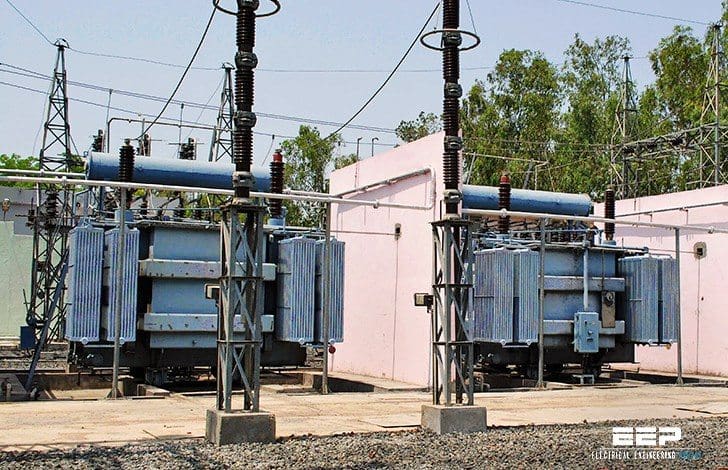 Paralleling and ferroresonance as special problems with power transformers (on photo: 3 single phase step down transformers; credit: cpri.in)
In order to parallel transformer banks, three criteria should be met:
1. Phasing
The high and low-voltage connections must have the same phasing relationship. On three-phase units, banks of different connection types can be paralleled as long as they have compatible outputs:
A delta – grounded wye may be paralleled with a grounded wye – grounded wye.
2. Polarity
If the units have different polarity, they should be wired accordingly. (Flip one of the secondary connections.)
3. Voltage
The phase-to-phase and phase-to-ground voltages on the outputs should be equal. Differences in turns ratios between the transformers will cause circulating current to flow through the transformers (continuously, even with zero load).
Before connecting the second transformer, crews should ensure that the secondary voltages are all zero or very close to zero (phase A to phase A, B to B, C to C, and the neutral to neutral).
For unequal impedances, the total bank must be derated (as stated by ABB, 1995) as:
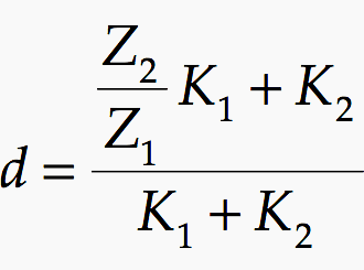
where:
- K1 = Capacity of the unit or bank with the larger percent impedance
- K2 = Capacity of the unit or bank with the smaller percent impedance
- Z1 = Percent impedance of unit or bank 1
- Z2 = Percent impedance of unit or bank 2
Ferroresonance occurrence
Ferroresonance is a special form of series resonance between the magnetizing reactance of a transformer and the system capacitance. A common form of ferroresonance occurs during single phasing of three-phase distribution transformers.
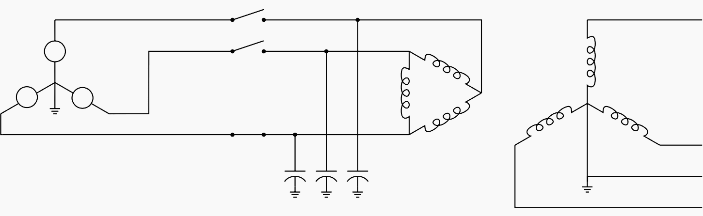
The transformer connection is also critical for ferroresonance. An ungrounded primary connection (see Figure 1) leads to the highest magnitude ferroresonance.
During single phasing (usually when line crews energize or deenergize the transformer with single-phase cutouts at the cable riser pole) a ferroresonant circuit between the cable capacitance and the transformer’s magnetizing reactance drives voltages to as high as five per unit on the open legs of the transformer.
The voltage waveform is normally distorted and often chaotic (see Figure 2).

The chance of ferroresonance is determined by the capacitance (cable length) and by the core losses and other resistive load on the transformer. The core losses are an important part of the ferroresonant circuit. Walling breaks down ferroresonance in a way that highlights several important aspects of this complicated phenomenon.
Consider the simplified ferroresonant circuit in Figure 3 below.
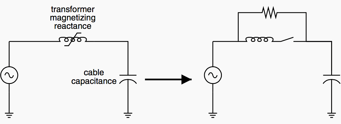
The transformer magnetizing branch has the core-loss resistance in parallel with a switched inductor. When the transformer is unsaturated, the switched inductance is open, and the only connection between the capacitance and the system is through the core-loss resistance.
This happens every half cycle (see Figure 4 for waveforms).

If the core loss is large enough (or the resistive load on the transformer is large enough), the charge on the capacitor drains off before the next half cycle, and ferroresonance does not occur. The transformer core does not stay saturated long during each half cycle, just long enough to release the trapped charge on the capacitor.
In modern silicon-steel distribution transformers, the flux density at rated voltage is typically between 1.3 and 1.6 T. These operating flux densities slightly saturate the core (magnetic steel fully saturates at about 2 T). Because the core is operated near saturation, a small transient (such as switching) is enough to saturate the core. Once started, the ferroresonance self-sustains. The resonance repeatedly saturates the transformer every half cycle.
Table 1 // Transformer primary connections susceptible to ferroresonance
| Susceptible Connections | Not susceptible |
| Floating wye | Grounded wye made of three individual units or units of triplex construction |
| Delta | Open wye – open delta |
| Grounded wye with 3, 4, or 5-legged core construction | Line-to-ground connected single-phase units |
| Line-to-line connected single-phase units |
Table 1 shows what types of transformer connections are susceptible to ferroresonance.
To avoid ferroresonance on floating wye – delta transformers, some utilities temporarily ground the wye on the primary side of floating wye – delta connections during switching operations.
Ferroresonance can occur on transformers with a grounded primary con- nection if the windings are on a common core such as the five-legged core transformer the magnetic coupling between phases completes the ferroresonant circuit. The five-legged core transformer connected as a grounded wye – grounded wye is the most common underground transformer configuration.
Ferroresonant overvoltages involving five-legged core transformers normally do not exceed two per unit.
Reference // Electric Power Distribution Handbook by T. A. Short (purchase hardcopy from Amazon)
Related electrical guides & articles


Edvard Csanyi
Hi, I'm an electrical engineer, programmer and founder of EEP - Electrical Engineering Portal. I worked twelve years at Schneider Electric in the position of technical support for low- and medium-voltage projects and the design of busbar trunking systems.I'm highly specialized in the design of LV/MV switchgear and low-voltage, high-power busbar trunking (<6300A) in substations, commercial buildings and industry facilities. I'm also a professional in AutoCAD programming.
Profile: Edvard Csanyi

ferroresonant over voltage occurs i have detected by multimeter during crane motor single phasing condition. it was to enough 650 v place of 415 v.
Dear,
Very frequently ferroresonce occurs in voltage trnsformers, when connected to the medium/generated voltage of a power generating system.
For instance, the polarizing voltage for voltage equiped protection is very sensitive to thios kind of phenomenon.
The way to overcome this is to connect a resistor in parallel with the VT output voltage ( similar to what indicated in your example above) and trying as much as possible not to overload the secondary thus keeping the burden very low.